Automatic cable deicing device based on cam transmission principle

A cam drive and cable technology, applied in circuit devices, cable installation, battery circuit devices, etc., can solve the problems of dangerous economic loss, high cost consumption, limited use range, etc., to ensure normal operation, save energy costs, energy less effective effect

Active Publication Date: 2020-09-04
台州壹品工业设计有限公司
View PDF11 Cites 7 Cited by
  • Summary
  • Abstract
  • Description
  • Claims
  • Application Information

AI Technical Summary

Problems solved by technology

[0002] Cables play a major role in power transportation and are the main components of power engineering. However, in recent years, the frequency and intensity of rain, snow and freezing disasters have gradually increased. When power transmission lines encounter rain, snow and freezing weather, the wires will be damaged. Icing, if a fast and effective deicing plan is not adopted, the thickness of the icing will continue to increase, and when it reaches a certain thickness, a rod down accident will occur, which will cause huge potential danger and cause great harm to the whole society Economic loss, the formation mechanism of wire icing is very complicated and related to various factors, such as temperature, humidity, wind speed, wind direction and rainfall, etc.
[0003] At present, domestic deicing technologies mainly include artificial deicing, high current heat generation and deicing, and mechanical deicing. However, manual deicing has a huge workload, low deicing efficiency, and high work intensity. Although the deicing effect is good, but the energy loss is large, the cost is high, and the cost performance is low. However, the existing mechanical deicing usually requires manual operation and offline charging, which leads to poor use and poor environment, such as mountainous areas. Difficult to use, limited range of use

Method used


Image

  • Automatic cable deicing device based on cam transmission principle
  • Automatic cable deicing device based on cam transmission principle
  • Automatic cable deicing device based on cam transmission principle

Examples


Embodiment Construction

[0026] The following will clearly and completely describe the technical solutions in the embodiments of the present invention with reference to the accompanying drawings in the embodiments of the present invention. Obviously, the described embodiments are only some, not all, embodiments of the present invention. Based on the embodiments of the present invention, all other embodiments obtained by persons of ordinary skill in the art without making creative efforts belong to the protection scope of the present invention.

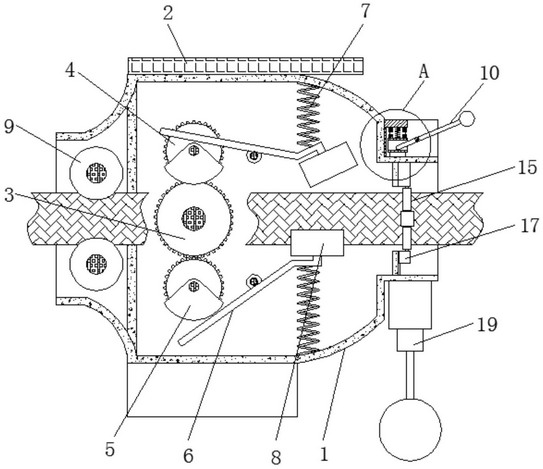
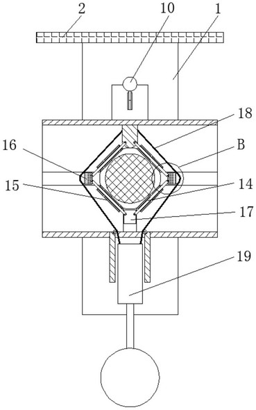
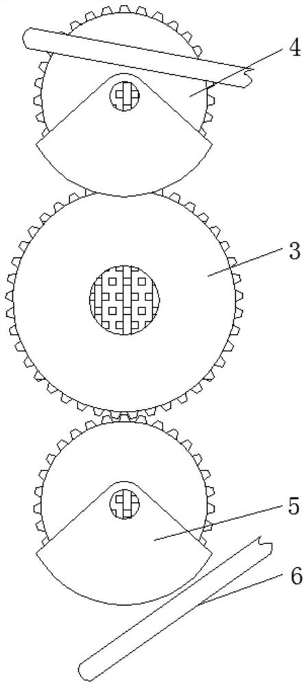
[0027] see Figure 1-5 , a cable automatic deicing device based on the principle of cam transmission, including a frame 1, a solar panel 2, a main gear 3, a connecting gear 4, a convex block 5, a lever 6, a tension spring 7, a concave hammer 8, and a power wheel 9. Control rod 10, lifting block 11, limit spring 12, contact block 13, connecting rod 14, guide wheel 15, slide block 16, positioning block 17, stay cord 18, counterweight block 19.

[0028] The posi...


PUM


Abstract

The invention relates to the technical field of cables, and further discloses an automatic cable deicing device based on the cam transmission principle. The device comprises a frame, the top of the frame is fixedly connected with a solar panel, and a main gear is movably connected in the frame. The outer portion of the main gear is connected with a connecting gear in an engaged manner, the outer portion of the connecting gear is fixedly connected with a convex block, and the outer portion of the convex block is movably connected with a driving lever. The outer portion of the driving lever is fixedly connected with a tension spring, the outer portion of the driving lever is fixedly connected with a concave hammer, and the inner portion of the frame is movably connected with a power wheel. Through the cooperative use of the main gear, the connecting gear, the convex block, the driving lever, the tension spring and the concave hammer, the effect of hammering the cable is achieved, and theice on the surface of the cable falls off, so that the cleanness of the surface of the cable is ensured, pole falling caused by the overweight of the cable is avoided, and the safety of a circuit iseffectively protected. Moreover, according to the automatic cable deicing device, the operation is simple, the energy effect is less, and the energy cost is effectively saved.

Description

technical field [0001] The invention relates to the technical field of cables, in particular to an automatic cable deicing device based on the principle of cam transmission. Background technique [0002] Cables play a major role in power transportation and are the main components of power engineering. However, in recent years, the frequency and intensity of rain, snow and freezing disasters have gradually increased. When power transmission lines encounter rain, snow and freezing weather, the wires will be damaged. Icing, if a fast and effective deicing plan is not adopted, the thickness of the icing will continue to increase, and when it reaches a certain thickness, a rod down accident will occur, which will cause huge potential danger and cause great harm to the whole society Economic loss, the formation mechanism of wire icing is very complex, related to various factors, such as temperature, humidity, wind speed, wind direction and rainfall. [0003] At present, domestic ...

Claims


Application Information

Patent Timeline
Patent Type & Authority Applications(China)
IPC IPC(8): H02G7/16H02J7/35
CPCH02G7/16H02J7/35
Inventor 沈施笠
Owner 台州壹品工业设计有限公司
Why Eureka
Try Eureka