Eureka AIR delivers breakthrough ideas for toughest innovation challenges, trusted by R&D personnel around the world.

Industrial refrigeration device for electrical cabinet and using method thereof

A technology for industrial refrigeration and electrical cabinets, which is applied to structural components of electrical equipment, electrical components, cooling/ventilation/heating transformation, etc., and can solve problems such as time-consuming, increased labor intensity of maintenance personnel, and damage to electrical components

Active Publication Date: 2020-09-04
珠海市圣亚制冷科技有限公司
View PDF5 Cites 3 Cited by
  • Summary
  • Abstract
  • Description
  • Claims
  • Application Information

AI Technical Summary

Problems solved by technology

[0003] There are a large number of electrical components inside the electrical cabinet, and the electrical components will generate a lot of heat when they work. If the electrical components cannot be cooled effectively and quickly, the heat will cause damage to the electrical components, accelerate the aging of the electrical components, and reduce the electrical components. service life, if a certain electrical component is damaged, the entire system will be paralyzed, so it is necessary to cool down the electrical components in the electrical cabinet. The traditional cooling method of the electrical cabinet has the following defects: 1. Only through the exhaust fan The air in the electrical cabinet is cooled. If it is a high temperature weather, the cooling effect is not obvious
2. Since the electrical components are fixed on the electrical component mounting plate, the back of the electrical component is attached to the electrical component mounting plate, so the exhaust fan cannot dissipate heat on the back of the electrical component, which will cause electrical The temperature of the back of the component is too high, which will cause damage to the electrical component
3. If the exhaust fan is used for exhaust, the air inlet must be installed. When the electrical cabinet is not in use, some living things such as insects and rats will enter the electrical cabinet through the air inlet, and the insects will be on the wires and other equipment in the electrical cabinet. Components cause damage and cause unnecessary losses, and it takes a lot of time and effort to troubleshoot and repair circuits and electrical components, which increases the labor intensity of maintenance personnel

Method used


Image

  • Industrial refrigeration device for electrical cabinet and using method thereof
  • Industrial refrigeration device for electrical cabinet and using method thereof
  • Industrial refrigeration device for electrical cabinet and using method thereof

Examples


Embodiment 1

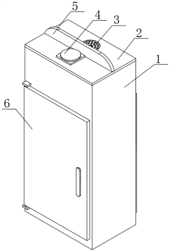
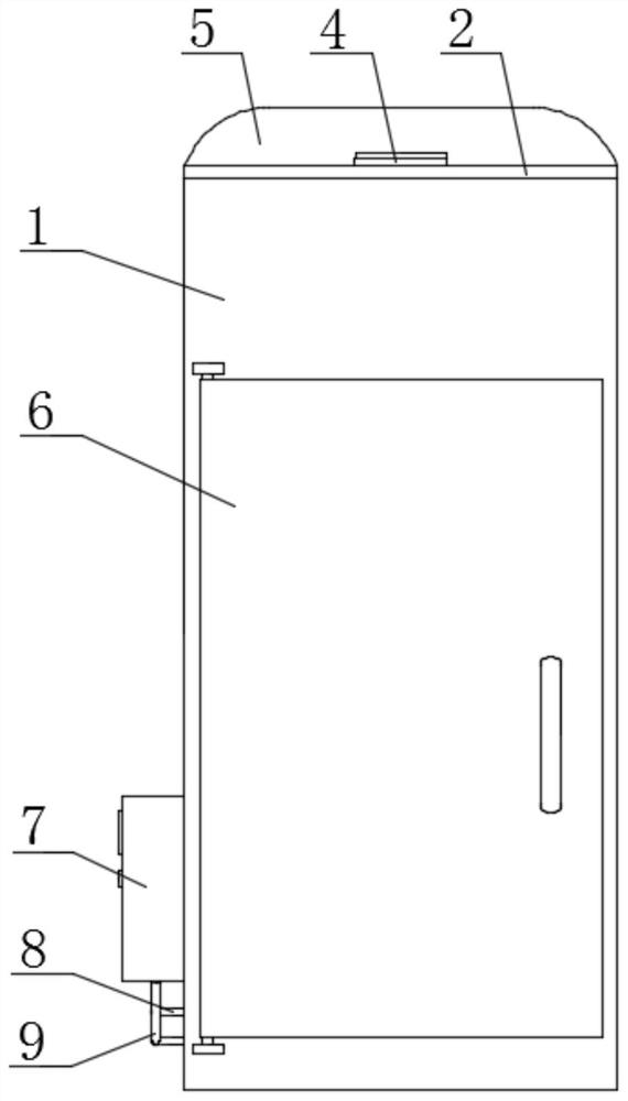
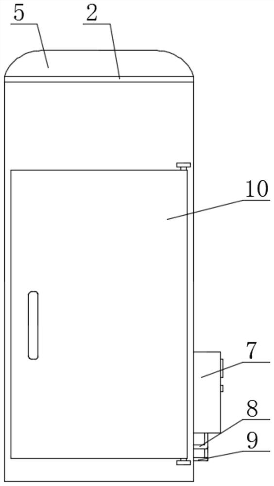
[0058] Embodiment one: if Figure 1-20 As shown, an industrial refrigeration equipment for electrical cabinets includes a cabinet body 1, door openings 15 are arranged on both sides of the cabinet body 1, and front door panels 6 and rear door panels 10 are respectively hinged on both sides of the cabinet body 1. Backboards 14 are fixedly installed on the inner walls of both sides and the inner wall of the bottom. The top of the cabinet body 1 is welded with a top cover 2. The bottom of the top cover 2 is in contact with the top of the backplane 14. The backplane 14 is close to the side of the front door panel 6. A plurality of electrical component mounting plates 16 arranged at equal intervals are fixedly installed, two support plates 11 are welded symmetrically on the top and bottom of the other side of the back plate 14, and two first racks are welded symmetrically on one side of the back plate 14 21. The same guide post 19 is welded on the sides of the two support plates 11...

Embodiment 2

[0072] Embodiment two: if Figure 21-25 As shown, an industrial refrigeration equipment for electrical cabinets, the difference between this embodiment and Embodiment 1 is: a horizontal plate 44 is welded on the top of one side of the back plate 14, and the top of the horizontal plate 44 is provided with a third through hole, and the third The inner wall of the through hole is slidably connected with a guide rod 36, and the top of the guide rod 36 passes through the third through hole, the first circular hole 47 and the filter plate 3 respectively and extends to the top of the top cover 2, and the top of the guide rod 36 is fixed. Sealing box 33 is installed, and the bottom of sealing box 33 contacts with the top of top cover 2, and the outer wall of guide rod 36 is vertically welded with round bar 37, and the top side of round bar 37 is welded with moving bar 45, and the side of moving bar 45 The top runs through the horizontal plate 44 and extends to the top of the horizonta...


PUM


Abstract

An industrial refrigeration device for an electrical cabinet comprises a cabinet body, door openings are formed at the two sides of the cabinet body correspondingly, a front door plate and a rear doorplate are hinged to the two sides of the cabinet body correspondingly, and back plates are fixedly installed on the inner walls of the two sides and the inner wall of the bottom of the cabinet body.The present invention also discloses a method of the industrial refrigeration device. The beneficial effects of the invention are that the industrial refrigeration device is simple in structure, according to the installation position of an electrical element with larger heating amount, the position of a cooling box can be adjusted, and the circulating cooling water can cool the back of the electrical element; a driving motor can drive a sealing box to separate from a top cover, a fan can enable the cooled air to carry out secondary cooling on the outer side of the electrical element, so that the electrical elements in the electrical cabinet can be rapidly cooled through the two-stage cooling, the heat dissipation efficiency is improved, the heat dissipation effect is good, heat dissipationis comprehensive, insects and mice can be prevented from entering the electrical cabinet to damage wires and other elements in the electrical cabinet when the electrical cabinet is not used, and theoperation is simple.

Description

technical field [0001] The invention relates to the technical field of cooling equipment for electrical cabinets, in particular to an industrial refrigeration equipment for electrical cabinets and a method for using the same. Background technique [0002] The electrical cabinet is a cabinet made of steel to protect the normal operation of components. The materials for making electrical cabinets are generally divided into two types: hot-rolled steel plates and cold-rolled steel plates. Compared with hot-rolled steel sheets, cold-rolled steel sheets are softer and more suitable for the production of electrical cabinets. Electrical cabinets are widely used mainly in chemical industry, environmental protection industry, power system, metallurgical system, industry, nuclear power industry, fire safety monitoring, transportation industry and so on. [0003] There are a large number of electrical components inside the electrical cabinet, and the electrical components will generat...

Claims


Application Information

Patent Timeline
Patent Type & Authority Applications(China)
IPC IPC(8): H05K7/20
CPCH05K7/20136H05K7/20218H05K7/20409
Inventor 不公告发明人
Owner 珠海市圣亚制冷科技有限公司
Why Eureka
Eureka Blog
Learn More