Special extrusion-force-adjustable injector for veterinarians

An adjustable, squeezing force technology, used in veterinary instruments, syringes, hypodermic instruments, etc., can solve problems such as the inability to automatically adjust the needle squeezing force

Inactive Publication Date: 2020-09-08
吴克坚
0 Cites 0 Cited by

AI-Extracted Technical Summary

Problems solved by technology

[0005] Aiming at the deficiencies of the prior art, the present invention provides a veterinary-specific adjustable extrusion force syringe, which has the advantages of automatically adjusting the extrusion force on the needle when the animal reacts violently, preventing the needle ...

Method used

Please refer to Fig. 1-4, a kind of veterinary special-purpose adjustable extruding syringe, comprises injection tube 1, and the material of injection tube 1 is lightweight plastics, can effectively prevent equipment from being corroded, greatly extended equipment The service life is reduced, and the production cost is reduced, which plays an indispensable role in the enterprise. The top of the injection tube 1 is interspersed with a push rod 2, and the bottom of the push rod 2 is fixedly connected with a pusher plate 3, and the bottom of the pusher plate 3 is fixed. The extruding rod 4 is connected, and the side of the extruding rod 4 is provided with a triangular protrusion, which squeezes the spring rod 11 when it moves down to a certain distance, and stores force for the spring rod 11. The bottom of the injection tube 1 is interspersed with an injection needle 5. The left side of the injection needle 5 is provided with teeth, and can be inserted by the clamp rod 7. The left side of the injection needle 5 is meshed with the clockwork wheel 6, and the left side of the injection needle 5 is located below the clockwork wheel 6. There is a clamping rod 7, the left side of the clamping rod 7 is fixedly connected with an extruding block 8, and the right side of the injection needle 5...

Abstract

The invention discloses an extrusion-force-adjustable injector special for veterinarians. The extrusion-force-adjustable injector comprise an injection tube; a push rod is inserted into the top of theinjection tube; the bottom of the push rod is fixedly connected with a liquid push plate; the bottom of the liquid pushing plate is fixedly connected with an extrusion rod; an injection needle is inserted into the bottom of the injection tube; the left side of the injection needle is engaged with a clockwork spring wheel; a pull rod is rotatably connected to the bottom of the spring rod; an ejector rod is slidably connected to the surface of an inner wheel of a ratchet wheel; an inflation plate is fixedly connected to one side, away from the ratchet wheel, of the ejector rod; an inflation boxis slidably connected to the side face of the inflation plate; and an inflation pipe is fixedly connected to one side, away from the injection needle, of the inflation box. According to extrusion-force-adjustable injector special for veterinarians, through cooperative use of the extrusion rod and a clamping rod, the effects that the extrusion force borne by the needle head is automatically adjusted and the needle head is prevented from being continuously inserted into an animal when the animal reacts violently are achieved.

Application Domain

Infusion syringesMedical devices +2

Technology Topic

PhysicsRatchet +3

Image

  • Special extrusion-force-adjustable injector for veterinarians
  • Special extrusion-force-adjustable injector for veterinarians
  • Special extrusion-force-adjustable injector for veterinarians

Examples

  • Experimental program(1)

Example Embodiment

[0026] The technical solutions in the embodiments of the present invention will be clearly and completely described below in conjunction with the accompanying drawings in the embodiments of the present invention. Obviously, the described embodiments are only a part of the embodiments of the present invention, rather than all the embodiments. Based on the embodiments of the present invention, all other embodiments obtained by those of ordinary skill in the art without creative work shall fall within the protection scope of the present invention.
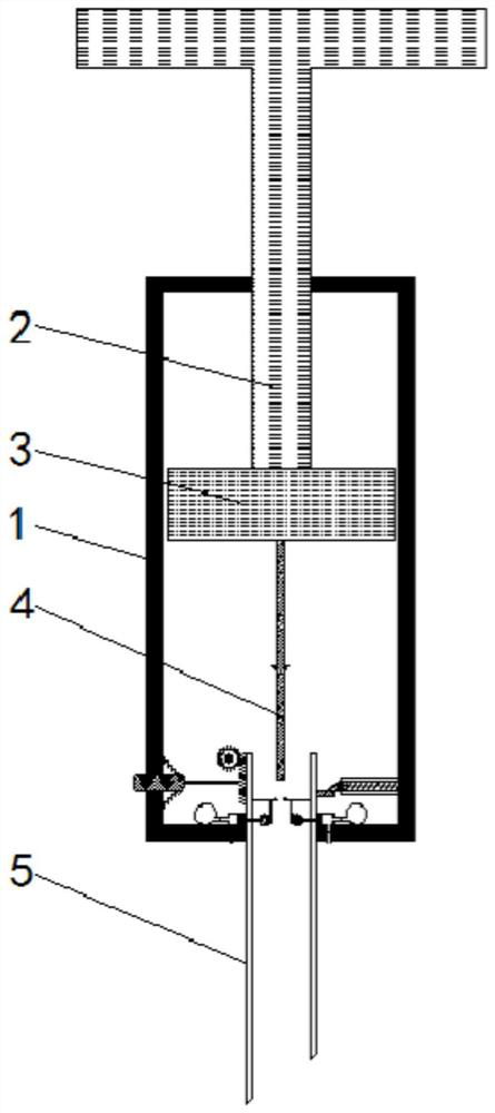
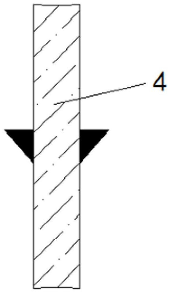
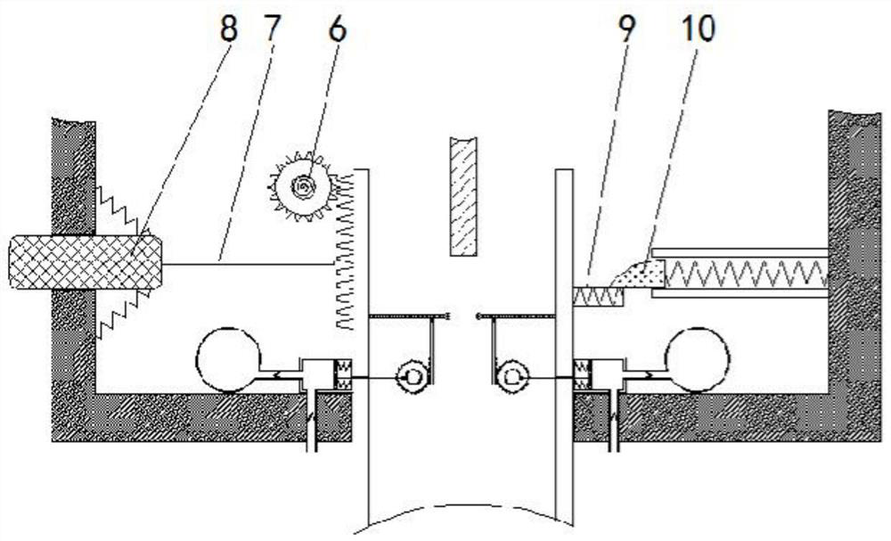
[0027] See Figure 1-4 , A veterinarian-specific syringe with adjustable squeezing force, including an injection tube 1. The material of the injection tube 1 is lightweight plastic, which can effectively prevent the equipment from being corroded, greatly prolong the service life of the equipment, and reduce the production cost. It has an indispensable role for the enterprise. The top of the injection tube 1 is interspersed with a push rod 2, the bottom of the push rod 2 is fixedly connected with a pusher plate 3, and the bottom of the pusher plate 3 is fixedly connected with an squeeze rod 4. The side of the rod 4 is provided with a triangular protrusion, which squeezes the spring rod 11 when it is moved down to a certain distance to accumulate the force of the spring rod 11. An injection needle 5 is inserted through the bottom of the injection tube 1, and the left side of the injection needle 5 is provided It has teeth and can be inserted by the clamping rod 7. The left side of the injection needle 5 is meshed and connected with a clockwork wheel 6. The left side of the injection needle 5 and below the clockwork wheel 6 is provided with a clamping rod 7, and the clamping rod 7 A squeeze block 8 is fixedly connected to the left side, and an elastic rod 9 is fixedly connected to the right side of the injection needle 5. The elastic rod 9 and the one-way clamp block 10 are clamped upward in one direction, and a one-way clamp block 10 is provided above the elastic rod 9 , The inner wall of the injection needle 5 is fixedly connected with a spring rod 11, the bottom of the spring rod 11 is rotatably connected with a pull rod 12, the side of the pull rod 12 is meshed and connected with a ratchet wheel 13, the ratchet wheel 13 and the pull rod 12 are unidirectionally engaged and driven upwards, the inner wheel of the ratchet wheel 13 The top rod 14 is slidingly connected to the surface. The material of the top rod 14 is stainless steel, which can effectively prevent the equipment from being corroded. The side of the top rod 14 away from the ratchet 13 is fixedly connected with an inflatable plate 15, and the side of the inflatable plate 15 is connected to the inflatable box through a return spring 16 is connected to make the ejector rod 14 continue to reciprocate left and right. The side of the inflatable plate 15 is slidably connected with an inflatable box 16, and the side of the inflatable box 16 is provided with a one-way air inlet pipe. When the inflatable plate 15 moves, the air is inhaled through the one-way air inlet pipe. When the airbag 18 is inflated through the inflation tube 17, an inflation tube 17 is fixedly connected to one side of the inflation box 16 away from the injection needle 5, and an airbag 18 is fixedly connected to the other side of the inflation tube 17.
[0028] When injecting drugs into the animal, press the squeeze block 8 so that the squeeze block 8 drives the clamping rod 7 to be inserted between the teeth provided on the side of the injection needle 5 to block the injection needle 5, and then insert the injection needle 5 Into the animal body, start to push the push rod 2 and inject the liquid medicine inside the injection tube 1 into the animal body through the push plate 3.
[0029] When the animal reacts violently during injection, the animal will drive the injection needle 5 to move. When the injection needle 5 is squeezed in parallel, the injection needle 5 will have a tendency to move upwards relative to the injection tube 1, passing through the one-way block 10 Blocked by the elastic rod 9, when the squeezing force reaches a certain level, the elastic rod 9 bends to a certain extent and moves upwards relative to the injection tube 1 over the one-way block 10. At this time, the injection needle 5 has reached the critical point of being able to continue to be inserted into the animal body. value.
[0030] Since the injection needle 5 moves up over the one-way block 10, the squeezing force of the injection needle 5 on the animal is removed, and it will not increase anymore. When the injection needle 5 moves up relative to the injection tube 1, it will be The bar wheel 6 produces meshing transmission. When the animal is not reacting violently, the injection needle 5 is driven to move to the initial position under the torsional force of the clockwork wheel 6, and the injection is continued without damaging the animal. During the reaction, the squeezing force of the needle is automatically adjusted to prevent the needle from continuing to be inserted into the animal.
[0031] During the injection process, the squeeze rod 4 is driven by the pusher plate 3 to move downward. Because the side of the squeeze rod 4 is provided with a triangular protrusion, when it contacts the spring rod 11, it will squeeze the spring rod 11. When the triangular protrusion is separated from the spring rod 11, the spring rod 11 suddenly loses its squeezing force, causing it to bounce up quickly, driving the rod 12, and the rod 12 engages with the ratchet 13 for transmission, so the rod 12 is fast Moving upward, it engages with the ratchet gear 13 and then disengages from the ratchet gear 13. Under the action of inertial force, the ratchet gear 13 continues to rotate, and the ejector rod 14 is pushed toward the inflatable box 16 through the arc-shaped protrusions set on the inner wheel surface. Under the action of the inflatable plate 15 and the return spring provided on the side, the ejector rod 14 continuously circulates left and right to drive the inflatable plate 15 to move synchronously. Because the side of the inflatable box 16 is provided with a one-way air inlet pipe, the movement of the inflatable plate 15 , The inflation box 16 inflates the airbag 18 through the inflation tube 17, and the airbag 18 expands to fill the side area of ​​the injection needle 5 located in the inner part of the injection tube 1, so that the push plate 3 injects all the liquid medicine inside the injection tube 1 The effect in the animal body.
[0032] Although the embodiments of the present invention have been shown and described, those of ordinary skill in the art can understand that various changes, modifications, and substitutions can be made to these embodiments without departing from the principle and spirit of the present invention. And variations, the scope of the present invention is defined by the appended claims and their equivalents.

PUM

no PUM

Description & Claims & Application Information

We can also present the details of the Description, Claims and Application information to help users get a comprehensive understanding of the technical details of the patent, such as background art, summary of invention, brief description of drawings, description of embodiments, and other original content. On the other hand, users can also determine the specific scope of protection of the technology through the list of claims; as well as understand the changes in the life cycle of the technology with the presentation of the patent timeline. Login to view more.
Why Eureka
Try Eureka