Shaft repair process

A process and repair material technology, which is applied to the device and coating of the surface coating liquid, can solve the problems of long manufacturing cycle, high manufacturing cost, restricting production continuity, etc., and achieves low maintenance cost, high repair efficiency, Achieve the effect of normal operation of the equipment

Pending Publication Date: 2020-09-08
中材萍乡水泥有限公司
View PDF7 Cites 2 Cited by
  • Summary
  • Abstract
  • Description
  • Claims
  • Application Information

AI Technical Summary

Problems solved by technology

In cement, chemical, mining and other industries, the shafts of crushers, fans, hoists and other equipment are affected by equipment failures such as large torque force or impact, assembly defects, and bearing damage, which often lead to fatigue wear of the transmission parts, resulting in shaft-axis hole fit When the position is damaged or the wear is large, the fit clearance of the shaft hole will increase, which will affect the normal operation of the equipment
[0003] The existing

Method used

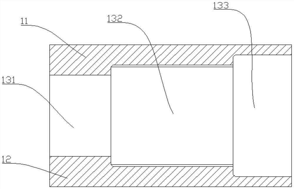
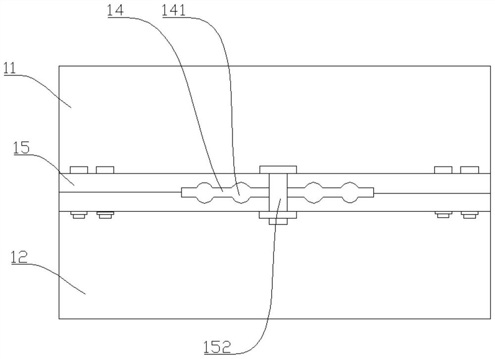
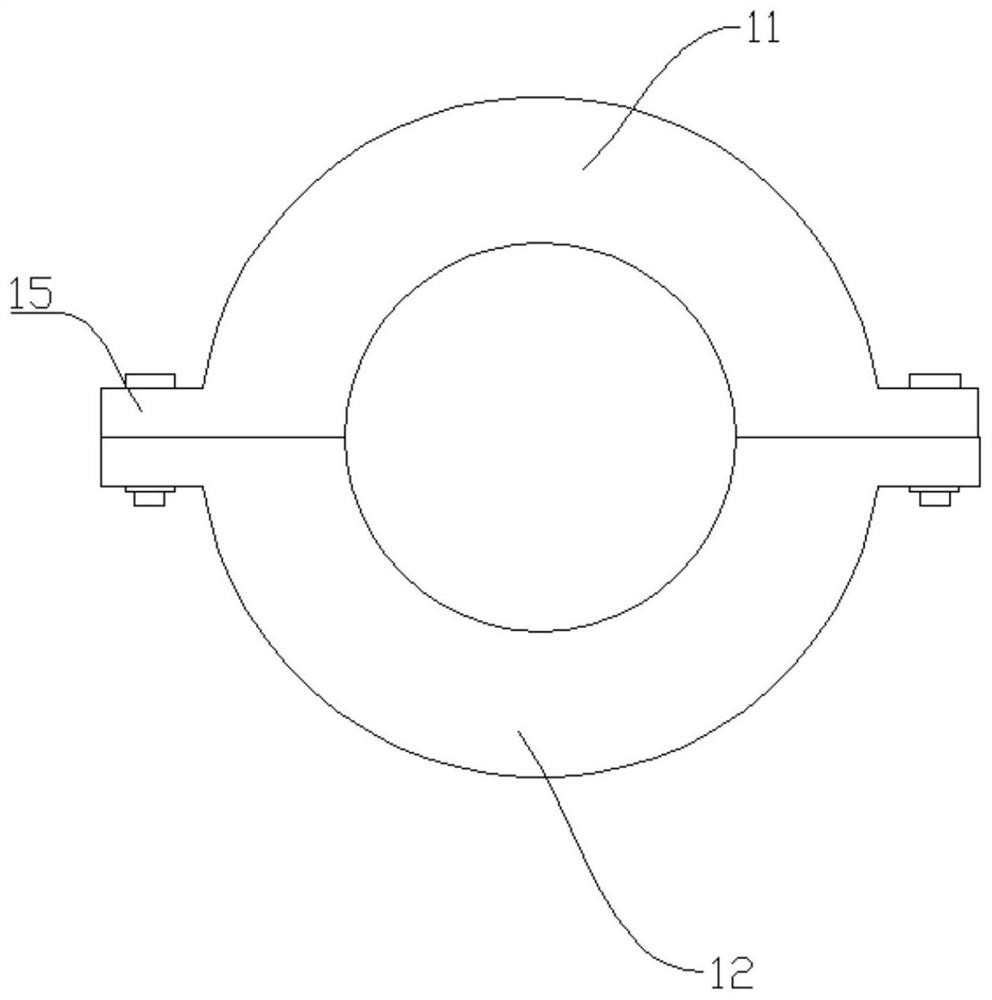

Image

  • Shaft repair process
  • Shaft repair process
  • Shaft repair process

Examples


Example Embodiment

[0029] The present invention will be further described in detail below with specific embodiments, but the present invention is not limited to the following specific embodiments.

[0030] In the description of the present invention, it should be understood that the terms "center", "longitudinal", "transverse", "upper", "lower", "front", "rear", "left", "right", " The orientation or positional relationship indicated by "vertical", "horizontal", "top", "bottom", "inner", "outer" etc. is based on the orientation or positional relationship shown in the drawings, and is only for the convenience of describing the present invention and The description is simplified, rather than indicating or implying that the pointed device or element must have a specific orientation, be constructed and operated in a specific orientation, and therefore cannot be understood as a limitation of the present invention. In addition, the terms "first", "second", etc. are only used for descriptive purposes, and ...


PUM


Abstract

The invention discloses a shaft repair process and relates to the technical field of worn shaft repair. The process comprises the steps that S1, an oxy-acetylene flame is used for roasting a shaft, and the temperature on the surface of the shaft is controlled below 90 DEG C till no sparks appear on the surface of the shaft; S2, a polishing machine is used for polishing a worn position of the shafttill metal primary color is exposed, and then absolute ethyl alcohol is used for cleaning the worn position of the shaft; S3, a repair material is smeared at the worn position of the shaft; S4, release oil is brushed on an inner ring of a die, then the die is arranged on the worn position of the shaft in a sleeving mode, and external force is applied to the die to extrude and discharge the redundant repair material on the shaft; and S5, after the repair material is shaped, the die is dismantled, the repaired shaft is obtained, and the repaired shaft is further finished to meet the process precision requirement. The shaft repair process has the advantages that the repaired shaft can be recovered to be within the range of +/-0.02mm of the original size, and matching between shaft holes canbe guaranteed; and moreover, repair efficiency is high, normal operation of equipment can be realized in a short time, and maintenance cost is low.

Description

technical field [0001] The invention relates to the technical field of repairing worn shafts, in particular to a shaft repairing process. Background technique [0002] The shaft is a cylindrical object that goes through the middle of the bearing or the middle of the wheel or the middle of the gear, but a small part is also square. A shaft is a mechanical part that supports and revolves with a rotating part to transmit motion, torque or bending moment. Generally, it is in the shape of a metal round rod, and each segment can have different diameters. The parts that make rotary motion in the machine are mounted on the shaft. In cement, chemical, mining and other industries, the shafts of crushers, fans, hoists and other equipment are affected by equipment failures such as large torque force or impact, assembly defects, and bearing damage, which often lead to fatigue wear of the transmission parts, resulting in shaft-axis hole fit When the position is damaged or the wear is l...

Claims


Application Information

Patent Timeline
IPC IPC(8): B23P6/00B05C13/02
CPCB23P6/00B05C13/02
Inventor 张昌煜李昌友周庆
Owner 中材萍乡水泥有限公司
Why Eureka
Try Eureka