Eureka AIR delivers breakthrough ideas for toughest innovation challenges, trusted by R&D personnel around the world.

Floating device and electric spindle

A floating device and floating shaft technology, which is applied in the direction of grinding/polishing safety devices, grinding machines, grinding machine parts, etc., can solve the problems of poor use of electric spindles, achieve improved deburring effect, and uniform cutting amount Effect

Pending Publication Date: 2020-09-08
苏州速科德电机科技有限公司
View PDF0 Cites 3 Cited by
  • Summary
  • Abstract
  • Description
  • Claims
  • Application Information

AI Technical Summary

Problems solved by technology

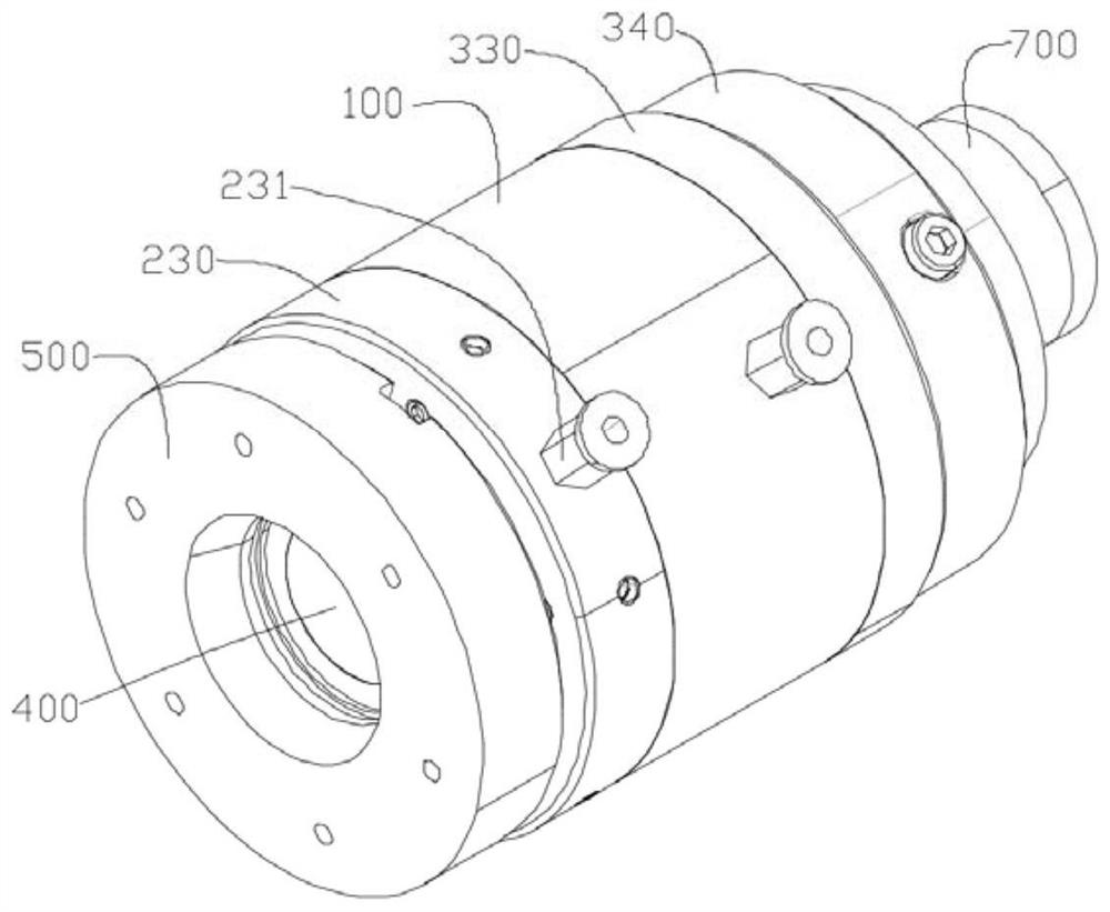
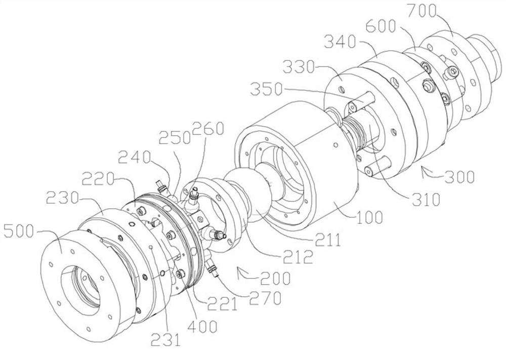
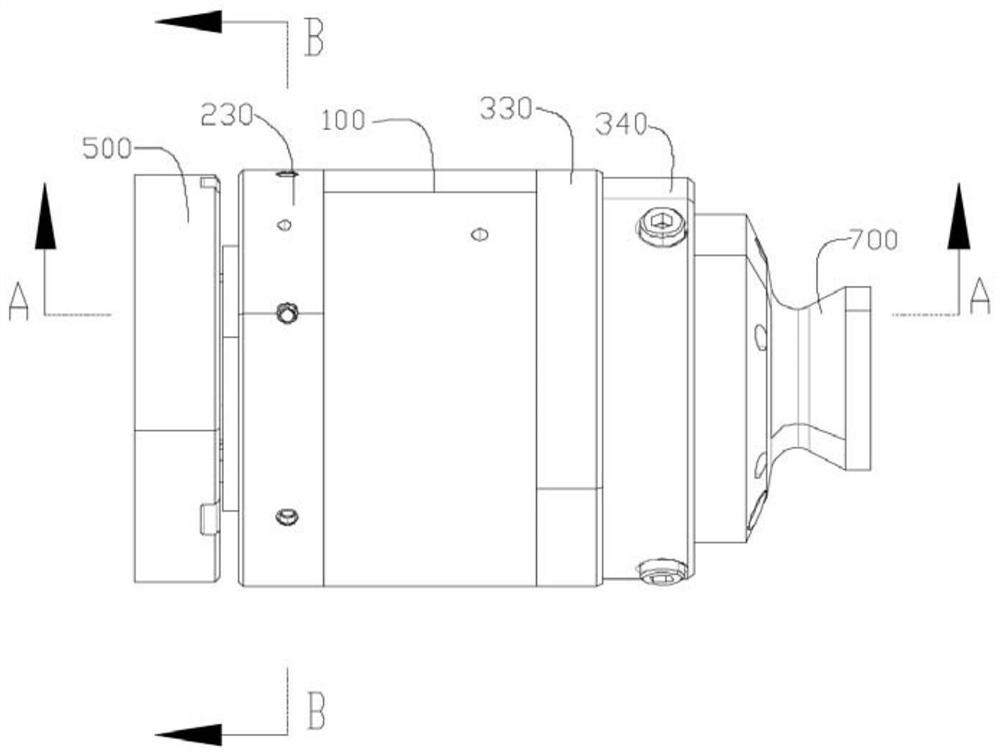
[0005] The purpose of the present invention is to provide a floating device and an electric spindle, so as to alleviate the technical problem of the poor use effect of the electric spindle in the prior art

Method used


Image

  • Floating device and electric spindle
  • Floating device and electric spindle
  • Floating device and electric spindle

Examples


Embodiment Construction

[0047] The technical solutions of the present invention will be clearly and completely described below in conjunction with the accompanying drawings. Apparently, the described embodiments are some of the embodiments of the present invention, but not all of them. Based on the embodiments of the present invention, all other embodiments obtained by persons of ordinary skill in the art without making creative efforts belong to the protection scope of the present invention.

[0048] In describing the present invention, it should be understood that the terms "center", "longitudinal", "transverse", "length", "width", "thickness", "upper", "lower", "front", " Back", "Left", "Right", "Vertical", "Horizontal", "Top", "Bottom", "Inner", "Outer", "Clockwise", "Counterclockwise", "Axial" , "radial", "circumferential" and other indicated orientations or positional relationships are based on the orientations or positional relationships shown in the drawings, which are only for the convenienc...


PUM


Abstract

The invention provides a floating device and an electric spindle, and relates to the technical field of electric spindle floating. The floating device comprises a mounting base, a radial floating assembly, an axial floating assembly and a floating shaft, wherein one end of the mounting base is connected with a robot through the axial floating assembly; the radial floating assembly is arranged at the other end of the mounting base; the floating shaft is inserted into the radial floating assembly; and the end, away from the mounting base, of the floating shaft is connected with a spindle floating connecting disc. The electric spindle comprises the floating device. The technical effect of the good using effect is achieved.

Description

technical field [0001] The invention relates to the technical field of electric spindle floating, in particular, to a floating device and an electric spindle. Background technique [0002] As the industry has been developing in the direction of Industry 4.0 (intelligent production), the goal of my country's Industry 3.0 (fully automated production) has not been fully realized, especially the front grinding process of the foundry industry. Due to the complex and irregular structure of the casting, the surfaces, holes and edges that need to be polished are distributed around the casting, making grinding difficult. [0003] At present, there are mainly the following methods for deburring existing castings. Manual grinding is used to remove burrs on castings. The disadvantages are that the production efficiency is low and the labor intensity is high; Yes, the manipulator can only grind the burrs on the castings in a fixed way, but will not automatically remove the burrs on the ...

Claims


Application Information

Patent Timeline
IPC IPC(8): B24B9/04B24B41/04B24B55/00
CPCB24B9/04B24B41/04B24B55/00
Inventor 朱开峰
Owner 苏州速科德电机科技有限公司
Why Eureka
Eureka Blog
Learn More