Vertical heat exchanger

A heat exchanger, vertical technology, applied in the field of vertical heat exchangers, can solve the problem of local heating of the upper tube sheet, and achieve the effect of solving local heating

Pending Publication Date: 2020-09-08
北京广厦环能科技股份有限公司
View PDF0 Cites 0 Cited by
  • Summary
  • Abstract
  • Description
  • Claims
  • Application Information

AI Technical Summary

Problems solved by technology

[0004] The purpose of the present invention is to provide a vertical heat exchanger, which can effectively solve the problem of local heating of the upper tube sheet due to gas accumulation

Method used


Image

  • Vertical heat exchanger
  • Vertical heat exchanger
  • Vertical heat exchanger

Examples


Embodiment 1

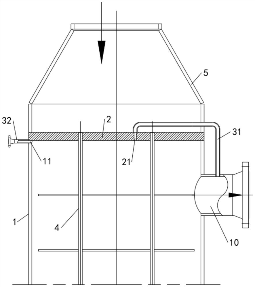
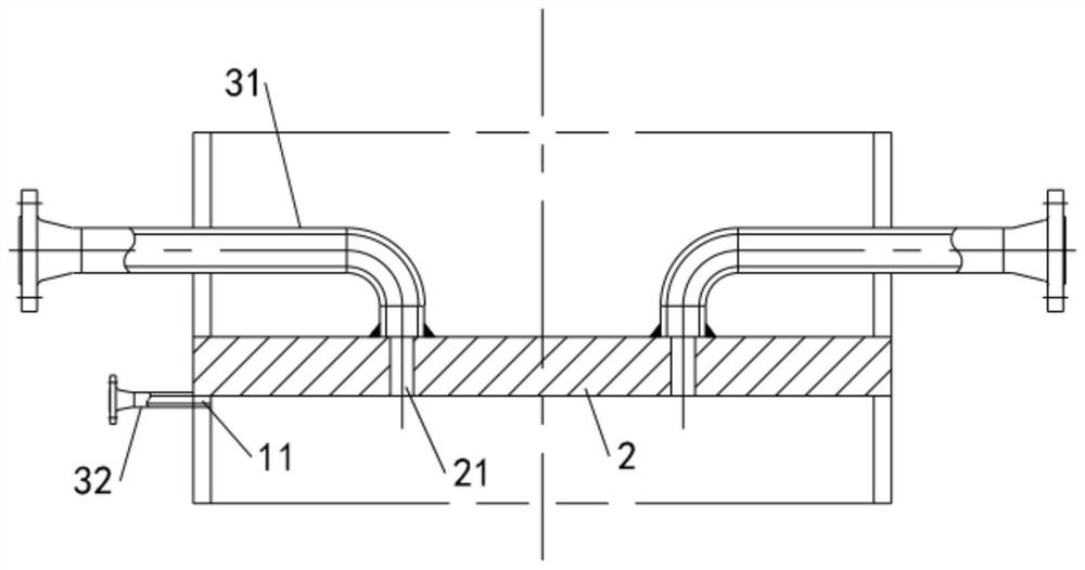
[0039] Such as figure 1 As shown, this embodiment provides a vertical heat exchanger, including a cylinder 1 with upper and lower ends open, an upper tube plate 2 for closing the opening at the upper end of the cylinder 1, and an upper tube plate 2 for closing the opening at the upper end of the cylinder 1. The lower tube plate with the opening at the lower end, the vertical heat exchanger also includes an upper tube box 5, a lower tube box and a plurality of heat exchange tubes 4, the upper tube box 5 is connected to the upper tube plate 2, and the lower tube box is connected to the lower tube plate , the upper tube box 5 is provided with a tube-side inlet, the lower tube box is provided with a tube-side outlet, the upper part of the cylinder body 1 is provided with a shell-side outlet 10, and the lower part of the cylinder body 1 is provided with a shell-side inlet; a plurality of heat exchange tubes 4 vertical One end of each heat exchange tube 4 is connected to the upper t...

Embodiment 2

[0048] The difference between this embodiment and the first embodiment lies in that the structure for exhausting the air below the piping area is different. Such as Figure 4 and Figure 5As shown, in this embodiment, a plurality of heat exchange tubes 4 are distributed according to a preset distribution form to form a gas flow channel 12, and the gas flow channel 12 communicates with the area of ​​the cylinder 1 directly below the edge area and directly below the pipe layout area .

[0049] In this embodiment, the second exhaust hole 11 communicates with the gas flow channel 12, and the gas in the cylinder 1 is led out through the gas flow channel 12, the second exhaust hole 11, and the second exhaust pipe 32, and at the same time realizes the piping area Exhaust below and below the edge area. In other embodiments, the first exhaust hole 21 can also be communicated with the gas flow channel 12 , and the gas inside the barrel 1 is led out through the gas flow channel 12 , t...

Embodiment 3

[0054] The difference between the present embodiment and the first embodiment lies in that the structure for exhausting the air below the edge area is different. Such as Figure 6 As shown, the exhaust structure includes a third exhaust hole 13 and a third exhaust pipe 33, wherein the third exhaust hole 13 is arranged on the cylinder body 1 and has a distance from the lower surface of the upper tube plate 2, One end of the third exhaust pipe 33 is inserted into the third exhaust hole 13 and connected to the cylinder body 1 for sending the gas under the edge area to the outside of the cylinder body 1 . It should be noted that the third exhaust pipe 33 may directly communicate with the outside atmosphere, or communicate with the shell side outlet 10 .


PUM


Abstract

The invention relates to the technical field of heat exchange, and discloses a vertical heat exchanger. The vertical heat exchanger comprises a barrel with an opening formed in the upper end, multipleheat exchange pipes arranged in the barrel and an upper pipe plate used for closing the opening. A pipe distribution area used for mounting of the heat exchange pipes and an edge area located outsidethe pipe distribution area are arranged on the upper pipe plate. An exhaust structure is further included and is used for at least conveying gas below the pipe distribution area out of the barrel. Through the exhaust structure, gas at least below the pipe distribution area is exhausted, operation is not limited by the influence of pipe plate thickness, heat exchange pipe distribution and other factors, on the premise of meeting the heat exchange requirement, gas below the upper pipe plate can be evenly exhausted, and the problem that the upper pipe plate is partially heated due to gas gathering is effectively solved.

Description

technical field [0001] The invention relates to the technical field of heat exchange, in particular to a vertical heat exchanger. Background technique [0002] The upper part of the shell side of the vertical heat exchanger and the lower side of the upper tube sheet are easy to accumulate gas, which will cause local overheating of the upper tube sheet, and even cause problems such as deformation of the upper tube sheet and cracking of the heat exchange tube, which will affect the normal heat exchange. run. [0003] For this reason, the existing technology usually sets an exhaust structure on the top of the vertical heat exchanger, but although the existing exhaust structure can export the gas below the upper tube sheet, due to the thickness of the tube sheet and the heat transfer on the tube sheet Due to the limitation of tube installation and other factors, the exhaust structure is only limited to the gas discharge in the edge area of ​​the upper tube sheet, and cannot tim...

Claims


Application Information

Patent Timeline
Patent Type & Authority Applications(China)
IPC IPC(8): F28D7/16F28F9/00
CPCF28D7/16F28F9/005
Inventor 韩军刘浩王春姜红梅刘致远
Owner 北京广厦环能科技股份有限公司
Why Eureka
Try Eureka