Direct-current switching device
A DC switch and switching technology, applied in the field of DC switch devices, can solve the problem of high cost, and achieve the effects of low cost, high versatility and fast breaking speed
- Summary
- Abstract
- Description
- Claims
- Application Information
AI Technical Summary
Problems solved by technology
Method used
Image

Examples
no. 1 example
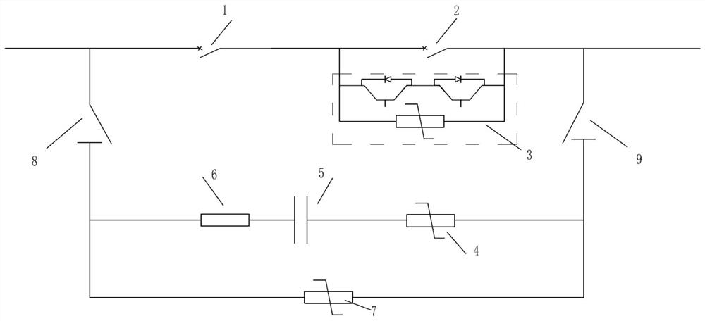
[0026] According to the first embodiment of the present invention, a DC switching device with controllable oscillating current in the transfer branch such as figure 1 shown. A DC switching device includes a first switch 1, a second switch 2, a bidirectional controllable switch module 3, a first lightning arrester 4, a capacitor 5, a resistor 6, a second lightning arrester 7, a third switch 8 and a fourth switch 9 . The second switch 2 is connected in parallel with the bidirectional controllable switch module 3, and then connected in series with the first switch 1 to form the main flow branch of the DC switch device; the first lightning arrester 4, the capacitor 5 and the resistor 6 are connected in series to form a DC switch In the transfer branch of the device, the two ends of the transfer branch are respectively connected in parallel to the two ends of the main flow branch through the third switch 8 and the fourth switch 9 connected in series. The second lightning arrester...
no. 2 example
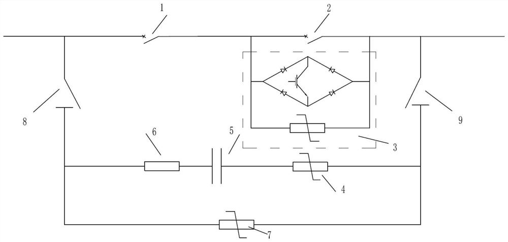
[0032] According to the second embodiment of the present invention, a DC switching device with controllable oscillating current in the transfer branch such as figure 2 shown. figure 2 neutralize figure 1 The same parts are denoted by the same reference numerals, the only difference is that figure 2 The middle and two-way full-control switch module adopts a bridge-type switch module composed of 1 controllable electronic component and 4 power diodes, which is connected in parallel with the third lightning arrester. The operation sequence of opening, closing and reclosing of the second embodiment is basically the same as that of the first embodiment, and will not be repeated here.
no. 3 example
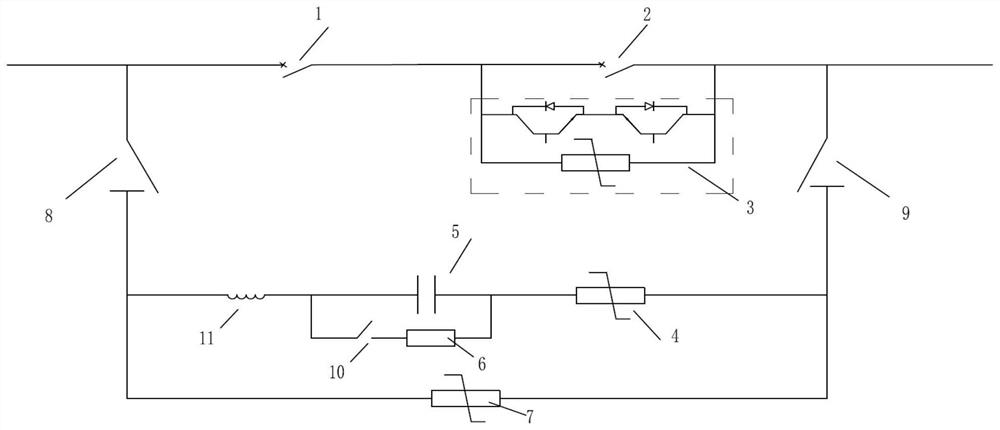
[0034] According to the third embodiment of the present invention, a DC switching device with controllable oscillating current in the transfer branch such as image 3 shown. image 3 neutralize figure 1 The same parts in are represented by the same reference numerals, the difference is that image 3 The energy storage module of the middle transfer branch is composed of the fifth switch 10 and the resistor 6 connected in parallel with the capacitor 5 , and the energy storage auxiliary module of the transfer branch is composed of an inductor 11 .
[0035] Before the closing operation, the fifth switch 10 is turned on by the controller, the capacitor 5 quickly discharges the resistor 6 through the fifth switch 10 , and then the fifth switch 10 is turned off. During the opening operation, when the capacitor 5 is charged, the inductor 11 acts as a current limiter. During the reclosing operation, if the fault circuit is not closed, the main flow branch directly carries the rated ...
PUM
 Abstract
Description
Claims
Application Information
 - R&D
- Intellectual Property
- Life Sciences
- Materials
- Tech Scout
- Unparalleled Data Quality
- Higher Quality Content
- 60% Fewer Hallucinations
Browse by: Latest US Patents, China's latest patents, Technical Efficacy Thesaurus, Application Domain, Technology Topic, Popular Technical Reports.
© 2025 PatSnap. All rights reserved.Legal|Privacy policy|Modern Slavery Act Transparency Statement|Sitemap|About US| Contact US: help@patsnap.com