Supercharge Your Innovation With Domain-Expert AI Agents!

Separation device gold wire bonding transition structure

A technology of gold wire bonding and transition structure, which is applied in the fields of radar, electronic equipment and communication, and can solve the problems of reduced integration of functional modules, increased loss of functional modules, and poor performance.

Active Publication Date: 2022-07-08
10TH RES INST OF CETC
View PDF19 Cites 0 Cited by
  • Summary
  • Abstract
  • Description
  • Claims
  • Application Information

AI Technical Summary

Problems solved by technology

This method has the following two disadvantages: 1. The size is large, because the transition includes two parts, that is, the gold wire bonding transition part from the separation device to the surface microstrip line and the coaxial transition part from the surface microstrip line to the dielectric integration
Therefore, its size is large, which in turn leads to a reduction in the integration of the entire functional module
2. Poor performance. Since the entire transition is formed by cascading two transitions, the loss is the superposition of the two transitions, which leads to an increase in the loss of the entire functional module.

Method used


Image

  • Separation device gold wire bonding transition structure
  • Separation device gold wire bonding transition structure

Examples


Embodiment Construction

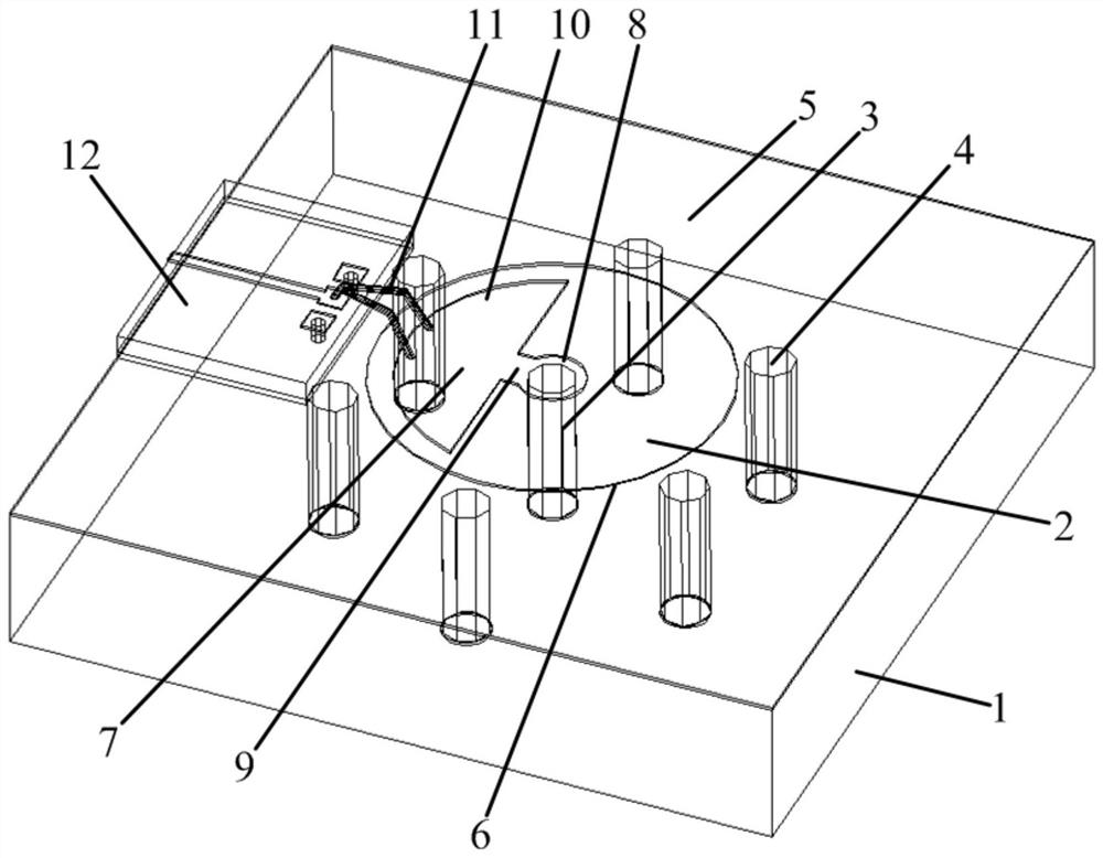
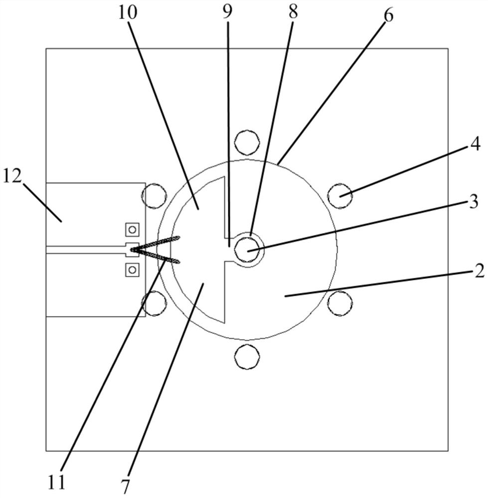
[0015] see figure 1 , figure 2 . In the preferred embodiment described below, a separation device gold wire bonding transition structure includes: a dielectric integrated coaxial body 2 disposed in the middle of the multilayer dielectric board 1 , and an inner conductor fixed in the center of the dielectric integrated coaxial body 2 The metallized vias 3 surround the inner conductor metallized vias 3, and the outer conductor metallized vias 4 are distributed in a circular array outside the disk surface of the dielectric integrated coaxial body 2, wherein: the upper end of the inner conductor metallized vias 3 is connected with a fan-shaped metal via Disc 7, the fan-shaped metal disc 7 is connected to the inner conductor of the inner conductor metallized via hole 3 through the fan handle collar 8 on the tail end of the fan handle 9, and the two branch lines of the bonding wire 11 pass through the arc surface of the fan surface 10. The two bonding balls are cascaded and conne...


PUM


Abstract

The invention discloses a gold wire bonding transition structure for separation devices, and aims to provide a gold wire bonding transition structure for separation devices with compact structure and low loss. The present invention is realized by the following technical scheme: a dielectric integrated coaxial body and a circular array of outer conductor metallized via holes are arranged outside the disk surface of the dielectric integrated coaxial body in the middle of the multilayer dielectric plate, and the upper end of the inner conductor metallized via hole is arranged. Connect a fan-shaped metal disk, the fan-shaped metal disk is connected to the inner conductor of the metallized via hole of the inner conductor through the fan handle sleeve on the tail end of the fan handle, and the two branch lines of the bonding wire pass through the two The bonding balls are cascaded and connected to the bonding points of the separation device to achieve a smooth transition from the separation device to the dielectric integrated coaxial body, and a circular notch is etched on the outer edge of the dielectric integrated coaxial body. The upper surface of the board forms the characteristics of flat capacitance, and the fan surface counteracts the parasitic inductance effect caused by the bonding of the gold wire and the gold wire through the fringe capacitance effect.

Description

technical field [0001] The invention relates to a gold wire bonding transition structure for separating devices in the fields of radar, electronic equipment, communication and the like. [0002] technical background [0003] With the rapid development of the communication industry, electronic systems are gradually developing in the direction of high density, high speed, high reliability, high performance and low cost. With the development of integrated circuits, the demand for miniaturization, intelligence, multi-function and high integration of microwave and millimeter wave functional modules is getting higher and higher. Traditional two-dimensional integrated modules can no longer meet this demand. As a representative of the three-dimensional integrated module of hybrid circuit integration technology, the bare chip and various components can be designed into microwave integrated circuits that meet the requirements in the three-dimensional, multi-layer dielectric substrate b...

Claims


Application Information

Patent Timeline
Patent Type & Authority Patents(China)
IPC IPC(8): H01L21/60H01L21/56
CPCH01L21/56H01L2021/60007H01L2224/48091H01L2924/00014
Inventor 杜明张凯
Owner 10TH RES INST OF CETC
Features
  • R&D
  • Intellectual Property
  • Life Sciences
  • Materials
  • Tech Scout
  • Unparalleled Data Quality
  • Higher Quality Content
  • 60% Fewer Hallucinations
Learn More