A multi-frequency multi-mode combined antenna

A combined antenna and antenna technology, applied in the field of communication, can solve the problems of dislocation and movement of the second antenna and the third antenna, antenna collision damage, no protection structure, etc., so as to reduce the dislocation and movement, realize fast positioning, and ensure smoothness. sexual effect

Inactive Publication Date: 2021-08-24
YIBIN UNIV
View PDF8 Cites 0 Cited by
  • Summary
  • Abstract
  • Description
  • Claims
  • Application Information

AI Technical Summary

Problems solved by technology

[0005] The purpose of the present invention is to provide a multi-frequency multi-mode combined antenna to solve the existing multi-frequency multi-mode combined antenna on the market proposed by the above-mentioned background technology. The installation space between two antennas, however, there is no corresponding protective structure on the outside. During installation and maintenance, it is easy to cause collision damage to its antennas, which is not conducive to the protection of multiple antennas. During installation, the second antenna It is not at the same height as the top of the third antenna, and there is no corresponding fixed structure for the top of the second antenna and the third antenna, which will easily cause dislocation and movement of the top of the second antenna and the third antenna, which is not conducive to the second antenna and the third antenna. Issues with third antenna stabilization settings

Method used


Image

  • A multi-frequency multi-mode combined antenna
  • A multi-frequency multi-mode combined antenna
  • A multi-frequency multi-mode combined antenna

Examples


Embodiment Construction

[0028] Based on the embodiments of the present invention, all other embodiments obtained by persons of ordinary skill in the art without making creative efforts belong to the protection scope of the present invention.

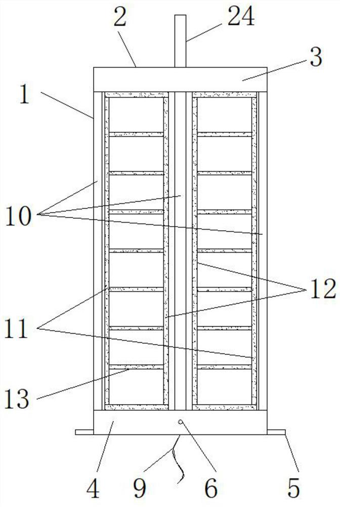
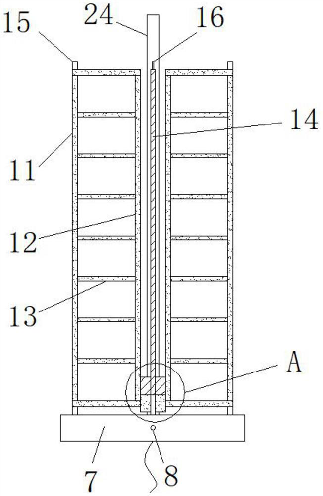
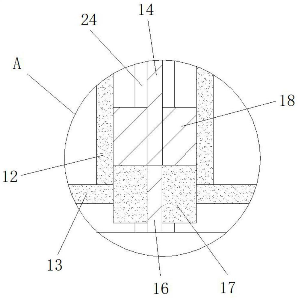
[0029] see Figure 1-9 , the present invention provides a technical solution: a multi-frequency multi-mode combined antenna, including an antenna body 1, a protective cover 2, a top limiting plate 3, a bottom limiting plate 4, a mounting block 5, screws 6, a mounting base 7, Threaded hole 8, connecting wire 9, support frame 10, first sub-antenna frame 11, first sub-antenna inner frame 12, first sub-antenna radiating arm 13, second sub-antenna frame 14, first limit head 15 , the second limit head 16, the first secondary antenna collar 17, the second secondary antenna collar 18, the second secondary antenna inner frame 19, the second secondary antenna radiation arm 20, the wire hole 21, the through hole 22, the limit Slot 23 and main antenna 24, the outside of a...


PUM


Abstract

The invention discloses a multi-frequency and multi-mode combined antenna, which comprises an antenna body, a protective cover, a mounting block, screws, connecting wires and wire holes. The outer part of the antenna body is provided with a protective cover, and the top of the protective cover is provided with a top Limiting plate, and the edge of the lower end surface of the top limiting plate is welded with a support frame, and the lower end of the supporting frame is welded to the edge of the upper surface of the bottom limiting plate at the same time, and the bottom limiting plate is installed on the base through screws and its inner side. The threaded holes are tightly connected, and the outer side of the bottom limiting plate is welded with a mounting block. The multi-frequency and multi-mode combined antenna can not only reduce the damage to the antenna by improving the structure of the existing multi-frequency and multi-mode combined antenna, but also can reduce the distance between multiple antennas by limiting the two ends of the antenna. The dislocation and movement of multiple antennas ensure the fixed setting among multiple antennas, and transmit signals of different frequency bands through the first antenna frame, the second antenna frame and the main antenna.

Description

technical field [0001] The invention relates to the technical field of communications, in particular to a multi-frequency and multi-mode combined antenna. Background technique [0002] Multi-frequency multi-mode combination antenna is a commonly used antenna in the field of communication. It can combine antennas of different frequency bands to realize the transmission and reception of multi-band signals. It is widely used in various communication equipment, such as comparison Document application number: CN201920645572.3, authorization announcement date: 20191115 A multi-frequency multi-mode combined antenna, which realizes the isolation between the second antenna and the third antenna through the difference in the direction of rotation of the helical structure and the spacing between the antennas. A short-circuit ring is added to isolate the second antenna from the first antenna, and to improve the radiation characteristics of the first antenna. The multi-frequency multi-mo...

Claims


Application Information

Patent Timeline
Patent Type & Authority Patents(China)
IPC IPC(8): H01Q1/42H01Q1/36H01Q1/50H01Q5/00H01Q21/00
CPCH01Q1/36H01Q1/42H01Q1/50H01Q5/00H01Q21/00
Inventor 邹永祥
Owner YIBIN UNIV
Why Eureka
Try Eureka