
Push-pull mechanism and working method thereof

A technology of push-pull mechanism and working method, which is applied in the field of signature cards, can solve the problems of increasing the cost of signature card cabinets and expensive prices, and achieve the effects of simple and stable structure, low manufacturing cost, and guaranteed stability

Pending Publication Date: 2020-09-11
SHANGHAI GOOAO ELECTRONIC TECHNOLOGY CORP
View PDF5 Cites 0 Cited by
  • Summary
  • Abstract
  • Description
  • Claims
  • Application Information

AI Technical Summary

Problems solved by technology

However, although the performance of the guide rail is superior, the price is relatively expensive, which greatly increases the cost of the entire signature card cabinet

Method used


Image

  • Push-pull mechanism and working method thereof
  • Push-pull mechanism and working method thereof
  • Push-pull mechanism and working method thereof

Examples


Embodiment Construction

[0040] In order to make the object, technical solution and effect of the present invention more clear and definite, the present invention will be further described in detail below with reference to the accompanying drawings and examples. It should be understood that the specific embodiments described here are only used to explain the present invention, not to limit the present invention.

[0041] It should be noted that the terms "first" and "second" in the description and claims of the present invention and the above drawings are used to distinguish similar objects, but not necessarily to describe a specific order or sequence. It should be understood that the data so used are interchangeable under appropriate circumstances. Furthermore, the terms "comprising" and "having", as well as any variations thereof, are intended to cover a non-exclusive inclusion.

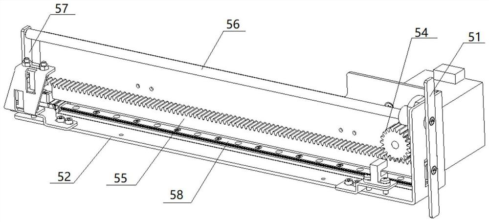
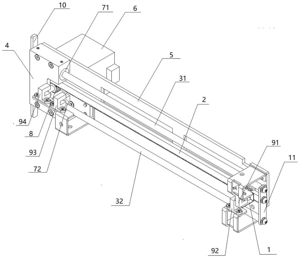
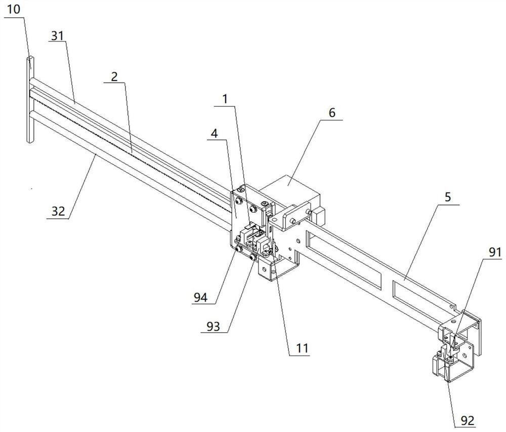
[0042] Such as Figure 2~3 As shown, the push-pull mechanism described in this application includes: a linear bearing ...


PUM


Abstract

The invention discloses a push-pull mechanism and a working mode thereof. The push-pull mechanism comprises a linear bearing retainer which is internally provided with a first linear bearing and a second linear bearing, a first guide rod is slidably sleeved with the first linear bearing in a penetrating mode, a second guide rod is slidably sleeved with the second linear bearing in a penetrating mode, one end of the first guide rod and one end of the second guide rod are both fixed to a front push plate, and the other end of the first guide rod and the other end of the second guide rod are bothfixed to a rear connecting plate; a rack is fixedly connected between the front push plate and the rear connecting plate, a gear is arranged at the driving end of the driving motor, and the gear drives the rack to do linear reciprocating motion through meshed teeth. The built-in linear bearing of the linear bearing retainer is adopted to provide a slideway for the sliding of the guide rods; therefore, the guide rail design in the prior art is replaced, the stability of the push-pull mechanism in the moving process is guaranteed, the cost is greatly reduced, and the push-pull mechanism has theadvantages of being simple and stable in structure, low in manufacturing cost and automatic and efficient in push-pull process and can be widely applied to signature card cabinets of financial institutions.

Description

technical field [0001] The application relates to the field of signature cards, in particular to a push-pull mechanism for a signature card cabinet and a working method thereof. Background technique [0002] The signature card is an important means of controlling payment risks in the RMB settlement account management method, and plays a pivotal role in the account transactions between banks and enterprises. [0003] Signature card cabinets are used in many banking institutions to store and manage the signature cards. Usually, the signature card of a unit is stored in a drawer box. When in use, the staff inputs the unit information to be searched, and the signature card cabinet automatically locates the stored drawer box according to its internal database. And under the control of the control system, the drawer box is rotated to the position to be pushed out, usually facing an automatic door structure on the signature card cabinet. The drawer box is pushed out from the auto...

Claims


Application Information

Patent Timeline
IPC IPC(8): A47B88/457A47B63/00
CPCA47B88/457A47B63/00
Inventor 武云鹏
Owner SHANGHAI GOOAO ELECTRONIC TECHNOLOGY CORP
Features
  • Generate Ideas
  • Intellectual Property
  • Life Sciences
  • Materials
  • Tech Scout
  • Unparalleled Data Quality
  • Higher Quality Content
  • 60% Fewer Hallucinations
Learn More