Assembled building beam and column connecting device

A beam-column connection and connection device technology, which is applied in buildings, protected buildings/shelters, building components, etc., can solve the problems of shock absorbing device offset and inability to effectively absorb shocks, etc.

Active Publication Date: 2020-09-11
SHANGHAI URBAN CONSTR VOCATIONAL COLLEGE
View PDF7 Cites 2 Cited by
  • Summary
  • Abstract
  • Description
  • Claims
  • Application Information

AI Technical Summary

Problems solved by technology

[0002] With the development trend of building industrialization, buildings with prefabricated structures are widely used, and when the prefabricated buildings are built, shock absorbing devices are generally installed between beams and columns, such as the patent with the publication (announcement) number CN10760505 1B, During installation, there will be a certain space between the beam and the column to install the shock absorber, but in the process of use, after the shock absorber is damaged, it is difficult to make the beam perpendicular to the shock absorber during the replacement of the shock absorber. The installation surface of the column, so that the installed shock absorbing device is offset, and cannot effectively play the role of shock absorption. A device that can adjust the angle between the beam and the column can effectively make the beam perpendicular to the column. Install the surface, and fix the beam, and leave a certain space between the beam and the column to install the shock absorber

Method used


Image

  • Assembled building beam and column connecting device
  • Assembled building beam and column connecting device
  • Assembled building beam and column connecting device

Examples


Embodiment Construction

[0012] In order to make the purpose, technical solutions and advantages of the embodiments of the present invention clearer, the technical solutions in the embodiments of the present invention will be clearly and completely described below in conjunction with the drawings in the embodiments of the present invention. Obviously, the described embodiments It is a part of embodiments of the present invention, but not all embodiments. Based on the embodiments of the present invention, all other embodiments obtained by persons of ordinary skill in the art without creative efforts fall within the protection scope of the present invention.

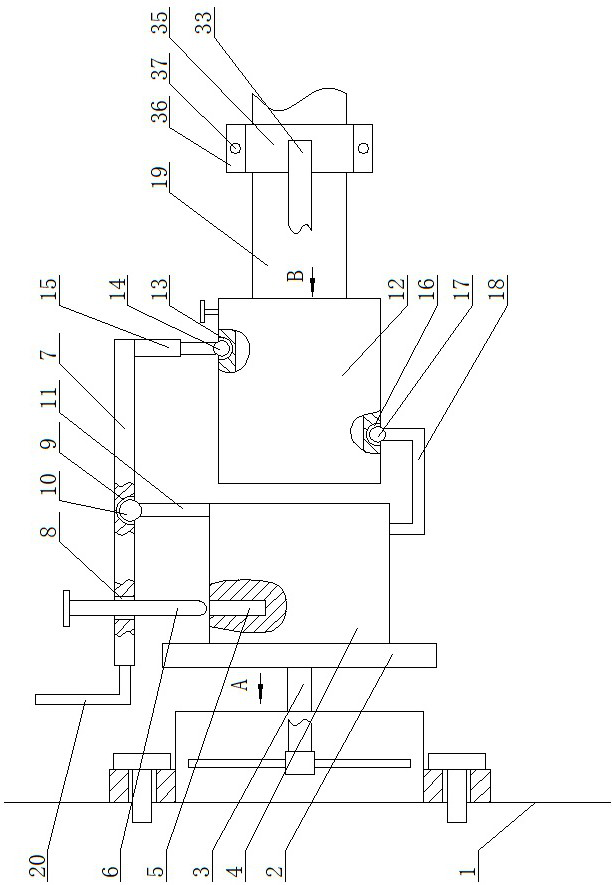
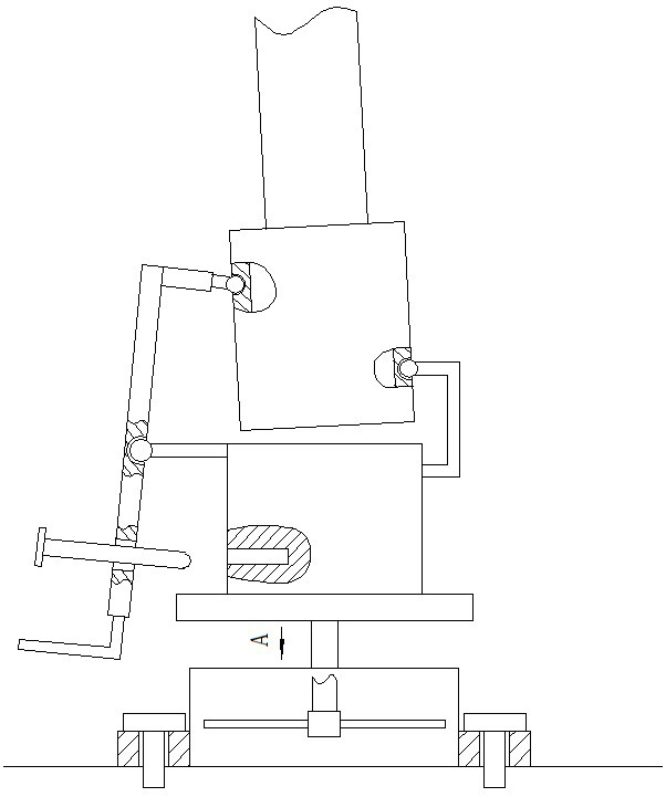
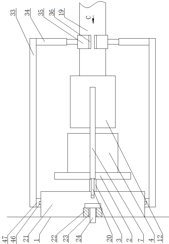
[0013] A prefabricated building beam-column connection device, as shown in the figure, includes a connection device, the connection device is connected with a column 1, a vertical circular plate 2 is arranged on the right side of the connection device, and the connection device is connected to the circular plate through a horizontal first sleeve 3....


PUM


Abstract

An assembled building beam and column connecting device comprises a connecting device. The connecting device is connected with a stand column, a vertical round plate is arranged on the right side of the connecting device, the connecting device is fixedly connected with the center of the left side surface of the round plate through a horizontal first sleeve, a cylindrical block is arranged at the center of the right side surface of the round plate through a bearing, a groove is formed in the position close to the left end of the top surface of the cylindrical block, a vertical plug pin is arranged above the groove, and a cross rod is arranged above the cylindrical block. A first through hole is formed in the position, corresponding to the plug pin, of the cross rod, the plug pin penetratesthrough the first through hole, the plug pin can move up and down in the first through hole, and a first spherical groove is formed in the center of the bottom surface of the cross rod. The axis of the cross beam and the mounting surface of the stand column can be perpendicular to each other without using other alignment tools, alignment and fixation can be realized by inserting the plug pin intothe groove, the aligned cross beam can be kept still through the connecting device, then the device is disassembled, and a certain gap can be reserved between the cross beam and the stand column for mounting a damping device.

Description

technical field [0001] The invention belongs to the field of beam-column connecting devices, in particular to an assembled building beam-column connecting device. Background technique [0002] With the development trend of building industrialization, buildings with prefabricated structures are widely used, and when the prefabricated buildings are built, shock absorbing devices are generally installed between beams and columns, such as the patent with the publication (announcement) number CN10760505 1B, During installation, there will be a certain space between the beam and the column to install the shock absorber, but in the process of use, after the shock absorber is damaged, it is difficult to make the beam perpendicular to the shock absorber during the replacement of the shock absorber. The installation surface of the column, so that the installed shock absorbing device is offset, and cannot effectively play the role of shock absorption. A device that can adjust the angle...

Claims


Application Information

Patent Timeline
Patent Type & Authority Applications(China)
IPC IPC(8): E04B1/58E04B1/98E04H9/02
CPCE04B1/58E04B1/98E04H9/021
Inventor 王宇星汤宇娇万雯
Owner SHANGHAI URBAN CONSTR VOCATIONAL COLLEGE
Why Eureka
Try Eureka