Automatic pushing type soil pressure balance pipe jacking machine

An earth pressure balance and self-propelled technology, which is applied in the direction of earth drilling, mining equipment, tunnels, etc., can solve the problems of inability to adjust the cutting size of the cutter head and poor adaptability, and achieve the effect of expanding the cutting range and improving work efficiency

Active Publication Date: 2020-09-11
BEIJING MUNICIPAL CONSTR
View PDF8 Cites 2 Cited by
  • Summary
  • Abstract
  • Description
  • Claims
  • Application Information

AI Technical Summary

Problems solved by technology

[0003] The existing pipe jacking machines generally cut the soil through the cutter head. However, due to different processing requirements, tunnels of different si

Method used


Image

  • Automatic pushing type soil pressure balance pipe jacking machine
  • Automatic pushing type soil pressure balance pipe jacking machine
  • Automatic pushing type soil pressure balance pipe jacking machine

Examples


Embodiment 1

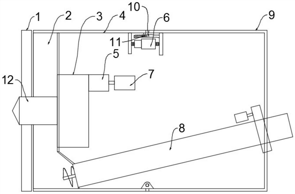
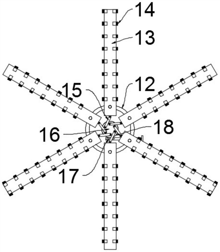
[0025] see Figure 1~2 , in an embodiment of the present invention, a self-propelled earth pressure balance pipe jacking machine includes an installation shell, a cutter head 1, a power unit that drives the cutter head 1 to rotate, and a delivery unit for outputting soil. The center of one end of the installation shell A main shaft 12 is installed for rotation, and the main shaft 12 is located on the shaft section outside the installation shell, and a plurality of cutter heads 1 are fixedly installed in the circumferential direction at equal intervals. The cutter head 1 includes a mounting plate 13 and two groups of tools installed symmetrically and equidistantly on the mounting plate 13. 14. Further, the cutter 14 of the adjacent cutter head 1 is misplaced to expand the effective cutting area. The power unit is installed in the installation shell and driven to connect the main shaft 12. The power unit includes a cutter head drive motor 7, a planetary reducer 5 and The power b...

Embodiment 2

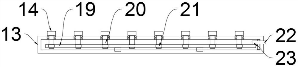
[0029] see Figure 3-5The difference between the embodiment of the present invention and embodiment 1 is that, further, since the cutters 14 are installed at intervals, the effective cutting area when the cutter head 1 rotates is smaller, and the mounting plate 13 is provided with a mounting cavity The end of the mounting plate 13 away from the main shaft 12 is rotated with a roller 22, the roller 22 is in contact with the soil, and the friction between the soil and the roller 22 makes the roller 22 rotate when the cutter head 1 rotates. Install the installation shaft 20 of the tool 14, the installation shaft 20 runs through the installation plate 13 and extends to the outside of the installation plate 13, the end of the installation shaft 20 located outside the installation plate 13 is detachably mounted with the tool 14, and the installation shaft 20 is fixedly equipped with a gear 21. There is a double-sided rack 19 between the front and rear symmetrical two sets of install...


PUM


Abstract

The invention discloses an automatic pushing type soil pressure balance pipe jacking machine, relates to the technical field of tunnel engineering, and mainly aims at solving the problem that the cutting diameter of an existing pipe jacking machine cannot be adjusted. An installing shell, cutter heads, a power unit driving the cutter heads to rotate and a conveying unit for outputting soil are included. The center position of one end of the installing shell is rotationally provided with a main shaft. The shaft section, located at the outer portion of the installing shell, of the main shaft isfixedly provided with the multiple cutter heads in the ring direction at equal interval. Each cutter head comprises an installing plate and two cutters symmetrically arranged on the installing plate at equal interval. An adjusting unit for adjusting the cutting diameter is further included and comprises an adjusting plate, connecting rods and a drive mechanism for driving the adjusting plate to rotate. The adjusting unit is arranged and comprises the adjusting plate, the connecting rods and the drive mechanism for driving the adjusting plate to rotate. The drive mechanism drives the adjustingplate to rotate, the adjusting plate drives the cutter heads to rotate through the connecting rods, the effective cutting length of the cutter heads is adjusted, and the purpose of adjusting the cutting diameter is achieved.

Description

technical field [0001] The invention relates to the technical field of tunnel engineering, in particular to a self-propelled earth pressure balance pipe jacking machine. Background technique [0002] With the development of urban construction, the population density has increased significantly, and there are more and more means of transportation. Urban traffic congestion restricts urban development. The pipe-curtain underground excavation method has become the research focus of underground space excavation. The pipe curtain construction method is a kind of non-excavation process. During the excavation process, the jacking device of a small-diameter pipe jacking machine is used to insert steel pipes horizontally into the space to be excavated to form a pipe curtain. [0003] The existing pipe jacking machines generally cut the soil through the cutter head. However, due to different processing requirements, tunnels of different sizes may require different types of pipe jacking...

Claims


Application Information

Patent Timeline
IPC IPC(8): E21D9/08E21D9/12
CPCE21D9/12E21D9/124E21D9/0874
Inventor 张龙林辉孙中伟冯勇冯波孙立迎段立群王志芬杨起帆郑进生杨松郑博枭李梓森
Owner BEIJING MUNICIPAL CONSTR
Why Eureka
Try Eureka