
Non-plugging fixed submersible sewage pump

A fixed, non-clogging technology, applied in the direction of non-variable pumps, non-volume pumps, pumps, etc., can solve the problems of accelerated sewage pumps, sewage pump blockage, blockage, etc., to achieve easy control, ingenious design, and small size Effect

Active Publication Date: 2020-09-11
湖北众堃科技股份有限公司
View PDF7 Cites 2 Cited by
  • Summary
  • Abstract
  • Description
  • Claims
  • Application Information

AI Technical Summary

Problems solved by technology

[0005] The purpose of the present invention is: in order to solve the problem that the fixed volume of the water collecting chamber for transporting liquid in the sewage pump mentioned in the background technology is inconvenient and easily leads to the blockage of the sewage pump, the volume of the water collecting chamber of individual sewage pumps can be changed, but the volume change corresponds to The transmission structure occupies a large area and the existing sewage pump lacks the function of collecting and discharging debris in the liquid, which is easy to accelerate the clogging of the sewage pump. A non-clogging fixed submersible sewage pump is proposed

Method used


Image

  • Non-plugging fixed submersible sewage pump
  • Non-plugging fixed submersible sewage pump
  • Non-plugging fixed submersible sewage pump

Examples


Embodiment 1

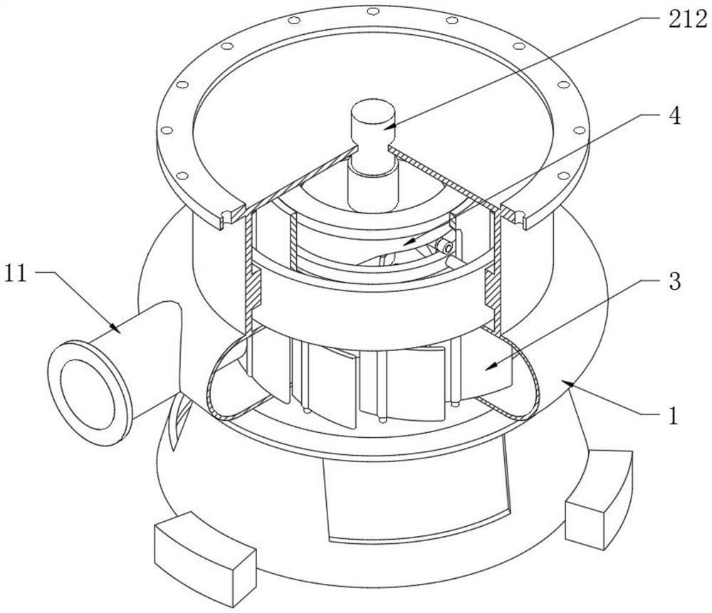
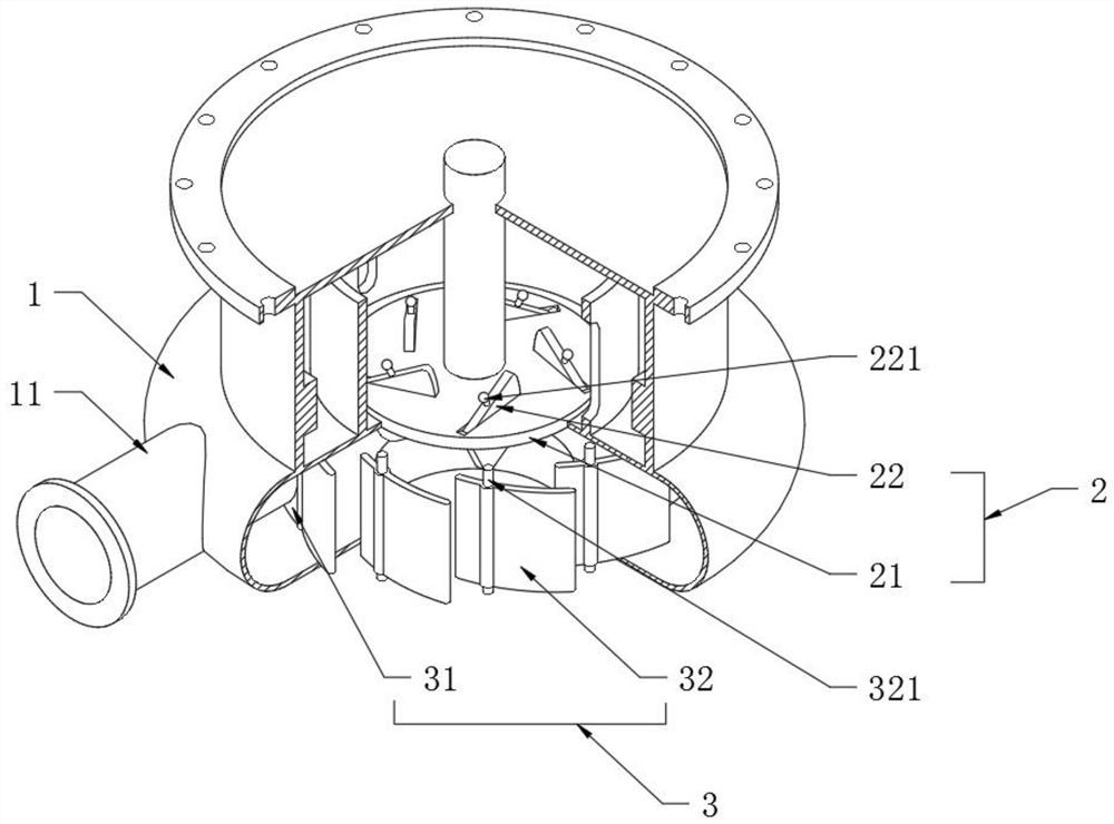
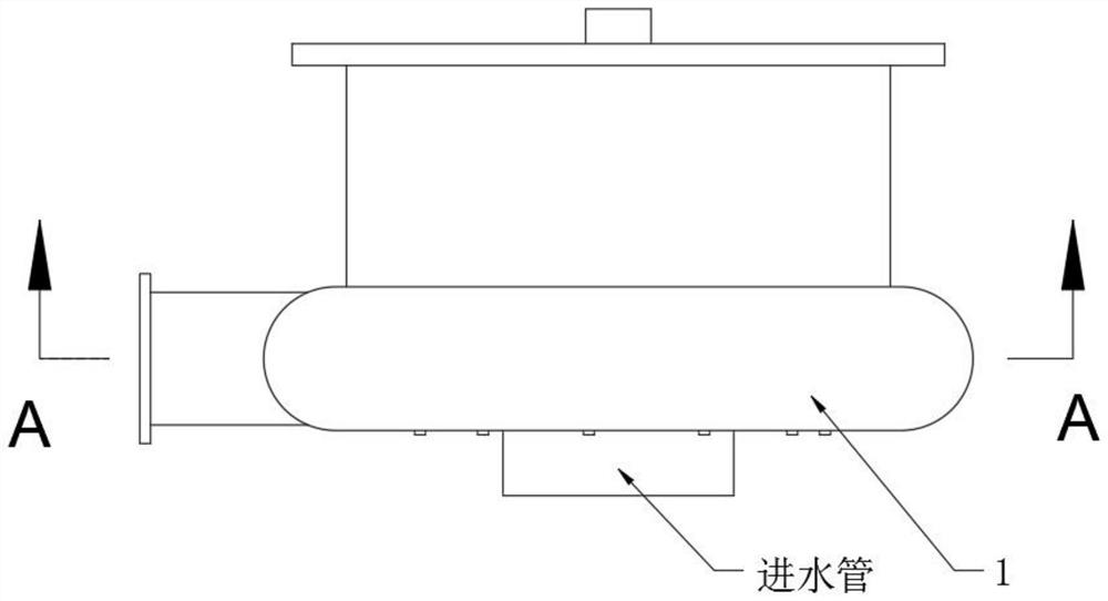
[0039] see Figure 1-7 , a non-clogging fixed submersible sewage pump, including a disc-shaped pump casing 1 and a sewage wheel 2, the bottom of the disc-shaped pump casing 1 is provided with a water inlet pipe, and the sewage wheel 2 rotates in the inner cavity of the disc-shaped pump casing 1 to turn the external The sewage is sucked into the disc-shaped pump casing 1 through the water inlet pipe, and the motor unit is installed on the upper part of the disc-shaped pump casing 1. The rotor on the motor unit is fixedly connected with the sewage wheel 2, and the supporting feet are installed on the lower part of the disc-shaped pump casing 1. Therefore, the combination of the above structures can constitute a complete sewage pump; this technical solution is to elaborate on the structure and cooperation of the disc-shaped pump casing 1 and the sewage wheel 2, and the outer wall of the disc-shaped pump casing 1 is provided with a sewage discharge pipe 11. A circular combination sl...

Embodiment 2

[0041] see Figure 6-12 Compared with Embodiment 1, the further description is that the linkage combination 4 includes a driving disc 41, a track sleeve 42, a return spring 43, a driving ring 44 and a driving sleeve 45. The middle part of the driving disc 41 is sleeved on the transmission shaft 212 and is axially Sliding fit, that is to say, the drive disc 41 can slide axially during the rotation of the drive shaft 212. The upper end surface of the disc-shaped pump casing 1 is fixed in the sleeve 15 with guide sleeves 16 and track sleeves 42 distributed coaxially. It is a T-shaped structure and is fixedly arranged on the top of the guide sleeve 16. The drive ring 44 is sleeved in the guide sleeve 16 and is located at the bottom of the track sleeve 42. It is worth noting that the inner diameter of the drive ring 44 is larger than the outer diameter of the lower end of the track sleeve 42. diameter, the return spring 43 is located at the bottom of the drive ring 44, and plays a ...

Embodiment 3

[0043] see Figure 13 The difference from Embodiment 1 is that the outer periphery of the disc-shaped pump casing 1 is provided with an arc-shaped notch 17, and the arc-shaped cover 5 matching the arc-shaped notch 17 is slidably connected in the circumferential direction. Slideways are set up on the periphery, and sliders are set up on the inner wall of the arc-shaped cover 5, so that the sliding arc-shaped cover 5 can realize the opening and closing of the arc-shaped gap 17. In embodiment 1, the blocked objects are thrown into the sewage collection In the cavity 13, when it is necessary to discharge the collected blockage, the handle on the sliding arc-shaped cover 5 can be used to scrape off the collected blockage with an external cleaning tool, so as to facilitate the discharge of the blockage.

[0044] Working principle: When in use, connect the top of the envelope 15 to the submersible motor unit through bolts, and fix the rotor on the motor unit to the drive shaft 212, t...


PUM


Abstract

The invention discloses a non-plugging fixed submersible sewage pump. A disc-type pump shell and a sewage-discharging wheel are included, and a sewage outlet pipe is arranged on the outer surface wallof the disc-type pump shell. In the non-plugging fixed submersible sewage pump, by arranging a circular combined sleeve in the disc-type pump shell, the circular combined sleeve is distributed coaxially with the sewage-discharging wheel and partitions an inner cavity of the disc-type pump shell into a water collecting cavity and a sewage collecting cavity, the sewage-discharging wheel is locatedin the water collecting cavity, wheel blades on the sewage-discharging wheel swing up and down, and the circular combined sleeve is composed of a first arc-shaped plate and second arc-shaped plates circumferentially distributed at equal intervals, wherein the second arc-shaped plates can rotate relative to the upper surface wall and the lower surface wall of the disc-type pump shell, when the second arc-shaped plates rotate, the water collecting cavity communicates with the sewage collecting cavity, the wheel blades swing up, the volume of the water collecting cavity increases to separate plugging materials, on the contrary, the volume of the water collecting cavity is reset for continuing the sewage discharging action, in the process, the effect of introducing the plugging materials in the water collecting cavity into the sewage collecting cavity is realized, and accordingly, the anti-plugging effect is realized.

Description

technical field [0001] The invention relates to the technical field of sewage treatment, in particular to a non-clogging fixed submersible sewage pump. Background technique [0002] In the sewage treatment system, the sewage pump is a widely used transmission tool. The sewage pump is a kind of pump product that is connected with the pump and the motor and submerged into the liquid at the same time. It is different from the general horizontal pump or vertical sewage pump. Compared with the sewage pump, which has a compact structure and a small footprint, the sewage pump has the characteristics of being able to transport liquids containing hard solids, fibers, and particularly dirty, sticky and slippery liquids, and is widely used in sewage treatment in various fields . [0003] At present, the above-mentioned sewage pumps are often used to transport liquids containing solid or fibrous substances with small volume and length. Since the sewage pump uses the sewage impeller to ...

Claims


Application Information

Patent Timeline
IPC IPC(8): F04D7/04F04D13/08F04D15/00F04D29/22F04D29/42F04D29/70
CPCF04D7/04F04D13/086F04D15/0027F04D29/2222F04D29/2261F04D29/426F04D29/708
Inventor 熊波张军鲁金伟
Owner 湖北众堃科技股份有限公司
Learn More