Solar heat dissipation device

A technology of heat dissipation device and solar energy, which is applied in transportation and packaging, lighting and heating equipment, heating/cooling equipment, etc. The effect of improving versatility and portability

Active Publication Date: 2020-09-11
康波波
View PDF7 Cites 1 Cited by
  • Summary
  • Abstract
  • Description
  • Claims
  • Application Information

AI Technical Summary

Problems solved by technology

[0004] Similar cooling equipment in the existing market, such as car curtains, are cumbersome to operate and have little cooling effect; there are also solar cooling fans (only draft, no cooling effect), which are used by clamping the equipment between the glass gaps of the car, solar panels Externally, the solar panel is used to drive the fan to discharge the hot air inside the car. This kind of equipment has little cooling effect, and the solar panel is external. Parking on the side of the road is easy to be damaged by curious people, and pedestrians will also accidentally pass by. I have encountered that there are still very few people using it at present, which is not conducive to popularization. The solution for using semiconductor cooling chips in the vehicle cab to dissipate heat and cool down is generally to connect the cold end of the semiconductor cooling chip with the cab, and connect the hot end of the semiconductor cooling chip to the cab. It communicates with the engine room or the outside of the vehicle. Although such a solution has a certain heat dissipation effect, the installation process requires professionals to remove the vehicle components and install the corresponding equipment. The installation process is cumbersome, the installation cost is high, and it is not conducive to maintenance and replacement. , the vehicle parts that have been dismantled may also affect its physical performance
[0005] As mentioned above, many devices and scenes that use semiconductor coolers for heat dissipation need to install semiconductor coolers. The installation process is cumbersome and time-consuming, and it is difficult to achieve widespread application.

Method used


Image

  • Solar heat dissipation device
  • Solar heat dissipation device
  • Solar heat dissipation device

Examples


Embodiment Construction

[0026] Below, the present invention will be further described in conjunction with the accompanying drawings and specific implementation methods. It should be noted that, under the premise of not conflicting, the various embodiments described below or the technical features can be combined arbitrarily to form new embodiments. .

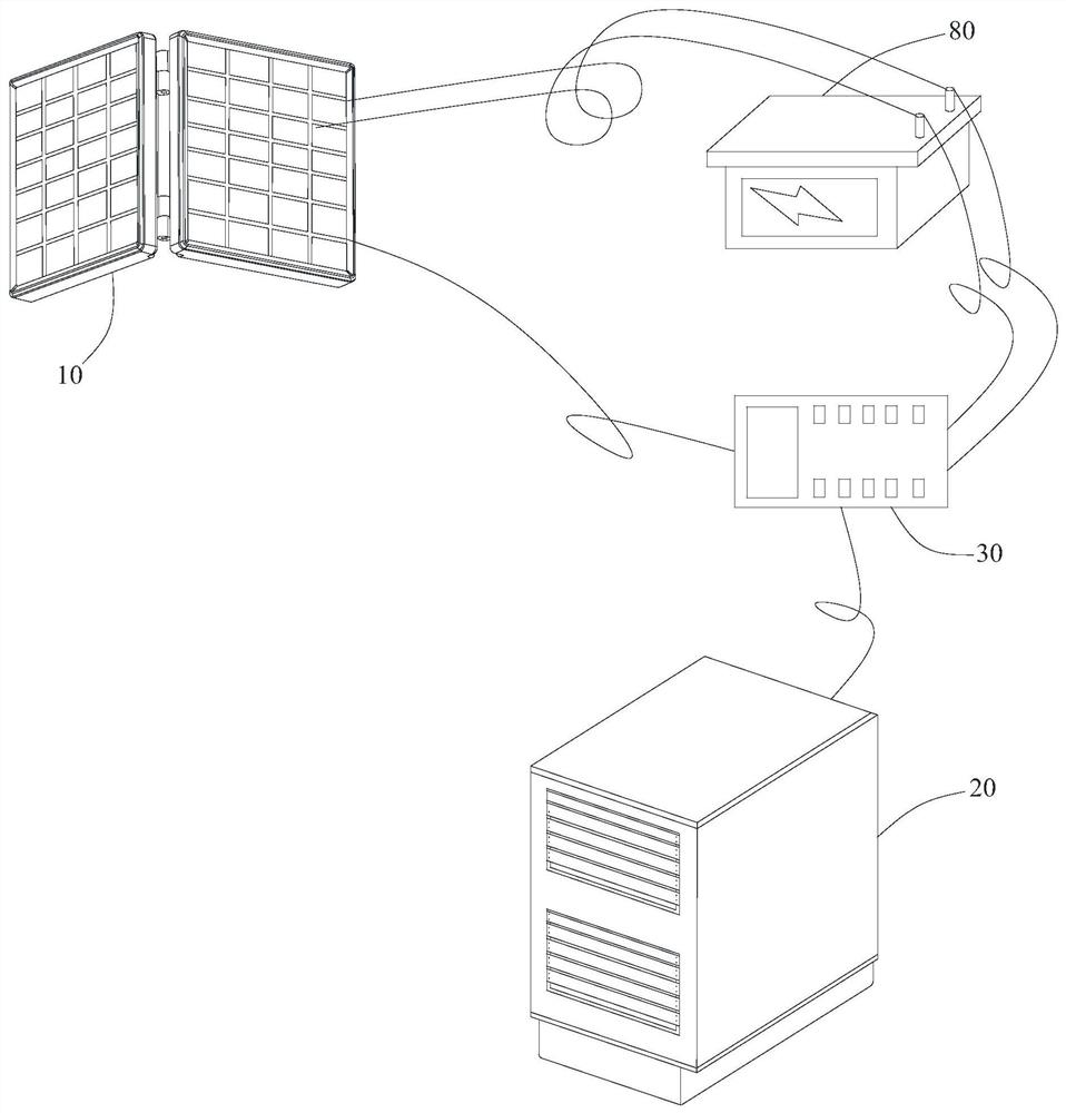
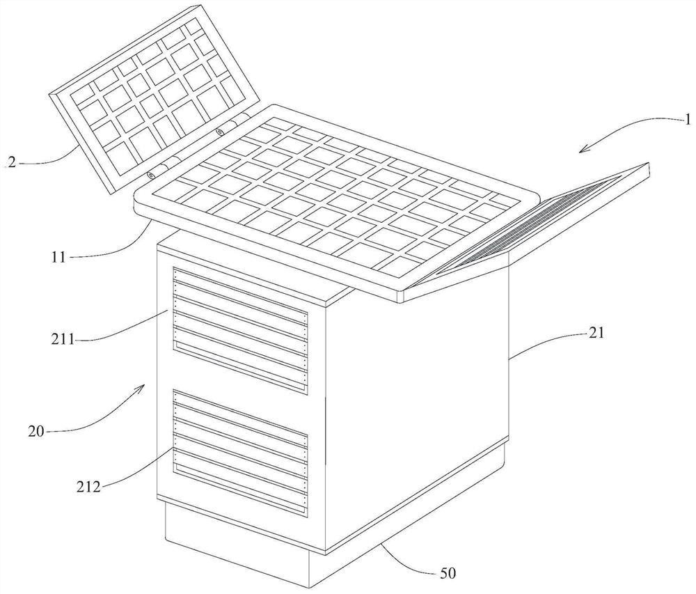
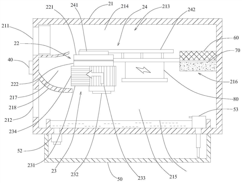
[0027] Such as Figure 1-Figure 3As shown, in order to make the semiconductor refrigeration sheet 22 more popular in the field of refrigeration and heat dissipation, the present invention discloses a solar heat dissipation device 23, which includes a solar power storage module, and the solar power storage module is used to transfer solar radiation energy through photoelectric effect or photochemical The effect is directly or indirectly converted into electrical energy, and the electrical energy is stored for use by the device. The solar power storage module includes a solar battery panel 10 and a battery 80. The battery 80 is electrically connected to ...


PUM

PropertyMeasurementUnit
Wire diameteraaaaaaaaaa

Abstract

The invention discloses a solar heat dissipation device, and belongs to environmental conditioning equipment. The solar heat dissipation device comprises a solar power storage module, a refrigerationmodule, a controller and a temperature detection module. The solar power storage module comprises a solar cell panel and a storage battery, and the storage battery is electrically connected with the solar cell panel. The refrigeration module is electrically connected with the storage battery and comprises an airtight shell and a semiconductor chilling plate, a hollow refrigeration cavity is formedin the airtight shell, and the semiconductor chilling plate is arranged in the refrigeration cavity. An air inlet and an air outlet which communicate with the refrigeration cavity are formed in the airtight shell, an air duct is formed between the air inlet and the air outlet, and the semiconductor refrigeration sheet is arranged in the air duct. The controller is in control connection with the solar power storage module and the refrigeration module. The temperature detection module is electrically connected with the controller. According to the solar heat dissipation device, the semiconductor chilling plate can be popularized more easily in different scenes, the semiconductor chilling plate can save more energy and is more environmentally friendly, and the cost problem caused by production and purchase of the device is solved.

Description

technical field [0001] The invention relates to an environment regulating device, in particular to a solar heat dissipation device. Background technique [0002] A semiconductor cooler, also called a thermoelectric cooler, is a heat pump. Its advantage is that there are no sliding parts, and it is used in some occasions where the space is limited, the reliability is high, and there is no refrigerant pollution. Utilizing the Peltier effect of semiconductor materials, when direct current passes through a galvanic couple formed by two different semiconductor materials in series, heat can be absorbed and released at both ends of the galvanic couple, which can achieve the purpose of cooling. It is a refrigeration technology that produces negative thermal resistance, is characterized by no moving parts, and is relatively reliable. [0003] Due to its superior performance, it is widely used in all walks of life and in various environments. Take cars as an example. At present, car...

Claims


Application Information

Patent Timeline
IPC IPC(8): F25B21/02F25B49/00B60H1/00B60H3/06
CPCF25B21/02F25B49/00B60H1/00478B60H1/00657B60H3/0608F25B2321/0251Y02T10/88
Inventor 康波波
Owner 康波波
Why Eureka
Try Eureka