Pipeline water pressure test system and test method

A hydraulic test and test system technology, applied in the direction of applying stable tension/pressure to test the strength of materials, measuring devices, instruments, etc., can solve problems that affect the safety of pipelines, inaccurate tests, and unqualified tests

Inactive Publication Date: 2020-09-11
陶忠梅
View PDF1 Cites 1 Cited by
  • Summary
  • Abstract
  • Description
  • Claims
  • Application Information

AI Technical Summary

Problems solved by technology

[0004] At present, the pipeline is full of water pressure inside, and the pipeline wall will expand and crack. The existing expansion of the pipeline is mainly through the observation of the pipeline wall with the naked eye. It is unqualified to observe the expansion and thickening of the pipeline wall. During the test, the pipeline Sometimes the wall will only produce a small amount of expansion, which is difficult to directly observe with the naked eye, which may easily lead to inaccurate tests and affect the safety of the pipeline in later use

Method used


Image

  • Pipeline water pressure test system and test method
  • Pipeline water pressure test system and test method
  • Pipeline water pressure test system and test method

Examples


Embodiment Construction

[0037] In order to make the technical means, creative features, goals and effects achieved by the present invention easy to understand, the present invention will be further elaborated below in conjunction with specific drawings. It should be noted that, in the case of no conflict, the embodiments and Features in the embodiments can be combined with each other.

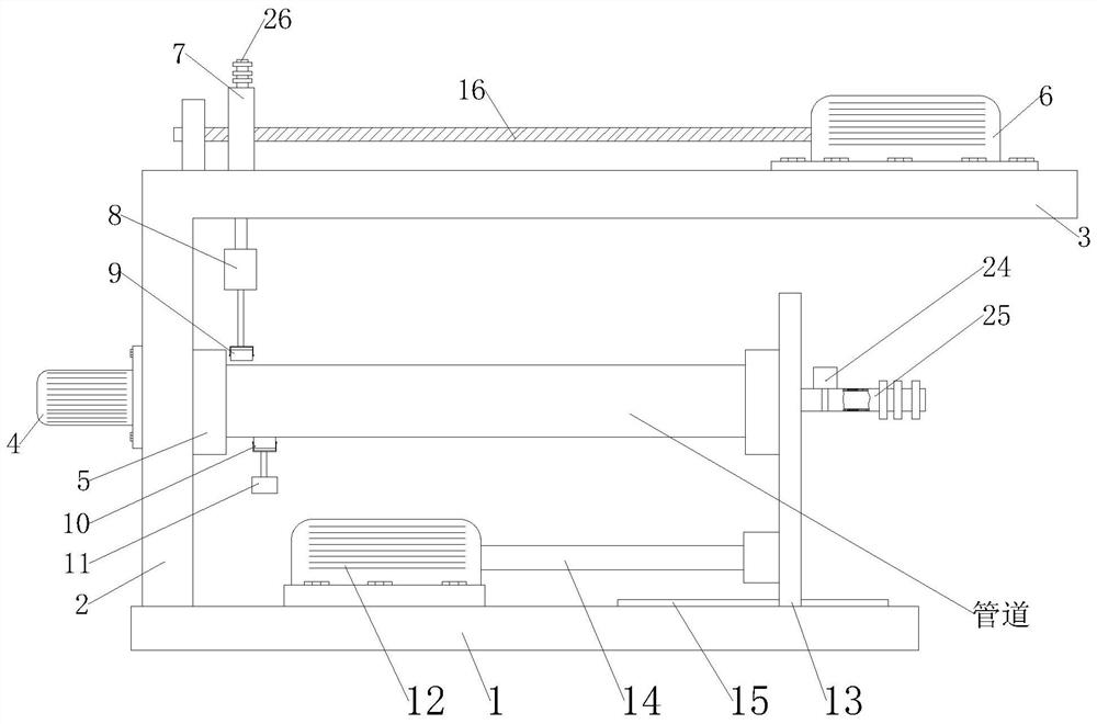
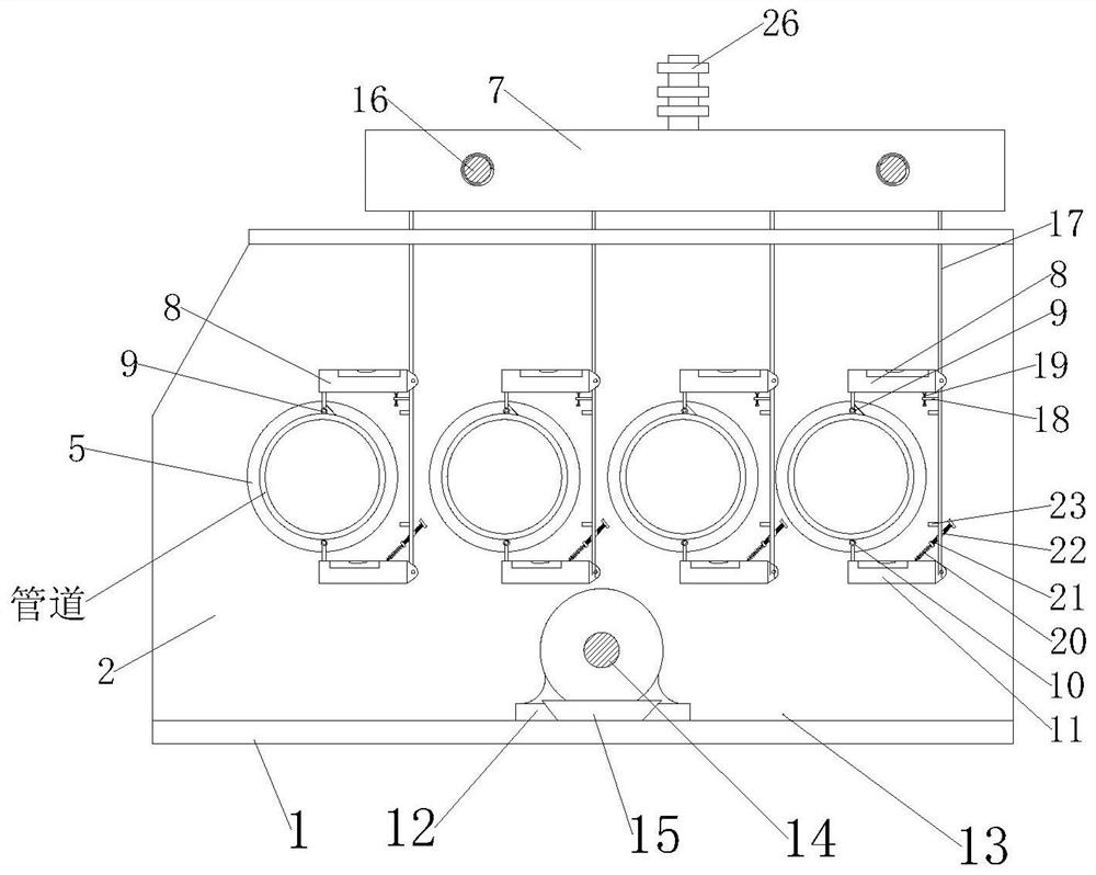
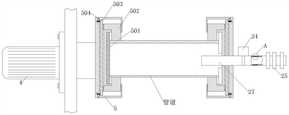
[0038] see Figure 1-7 , is a schematic diagram of the overall structure of a pipeline hydraulic test system and test method;

[0039] A pipeline hydrostatic test system, comprising a bottom support plate 1 placed horizontally on the ground, the top of the bottom support plate 1 is provided with a support rib 2 standing upright on the top of the bottom support plate 1, and the top of the support rib 2 is provided with The top support plate 3 is horizontally fixed, and the top of the top support plate 3 is provided with a plurality of through long holes, and two adjacent long holes are arranged at equal intervals on t...


PUM


Abstract

The invention provides a pipeline water pressure test system and a test method, which relate to the technical field of conveying pipeline safety measurement. The systemcomprises a bottom supporting plate which is horizontally placed on the ground, the top end of the bottom supporting plate is provided with a supporting rib plate erected at the top end of the bottom supporting plate, a horizontally-fixed top supporting plate is arranged at the top end of the supporting rib plate, a plurality of through long holes are formed in the top end of the top supporting plate, every two adjacent long holes are formed in the top end of the top supporting plate at equal intervals, and threaded lead screws parallel to the long holes are arranged at the top end of the top supporting plate. An exhaust hole is formed in the middle of anair nozzle,a guide plate is hinged to the inner wall of the exhaust hole, the angle of the guide plate in the exhaust hole is controlled by the guide plate through a third adjusting screw, the blowing-out direction of the exhaust hole is controlled by changing the swing angle of the guide plate, airflow is guided to the outer wall of the pipeline, impurities on the outer wall of the pipeline are removed, and operation simplicity is improved.

Description

technical field [0001] The invention relates to the technical field of transportation pipeline safety measurement, in particular to a pipeline hydraulic test system and test method. Background technique [0002] After the production of the pipeline is completed, the pipeline should be subjected to a hydrostatic test according to the design requirements. The main purpose of the pressure test is to check the mechanical properties, tightness and vacuum holding performance of the pipeline. Except for the vacuum pipeline system and the special pipeline system with fire protection requirements, most pipelines only have strong requirements on the strength and tightness of the pipeline. In order to test the mechanical properties and strength tests of pipelines, hydrostatic testing is generally used. [0003] At present, the method for testing the mechanical properties of pipelines is mainly to inject water pressure into the pipeline for testing, such as a pipeline water pressure te...

Claims


Application Information

Patent Timeline
Patent Type & Authority Applications(China)
IPC IPC(8): G01N3/12
CPCG01N3/12G01N2203/0003G01N2203/0019G01N2203/0048G01N2203/0075G01N2203/0274G01N2203/0605
Inventor 陶忠梅李晨
Owner 陶忠梅
Why Eureka
Try Eureka