
Dual-channel data transmission device and system

A data transmission device and data transmission technology, applied in the field of data transmission, can solve the problem of single function of the download line structure, and achieve the effect of solving single function and avoiding idleness

Pending Publication Date: 2020-09-11
INST OF MICROELECTRONICS CHINESE ACAD OF SCI
View PDF4 Cites 2 Cited by
  • Summary
  • Abstract
  • Description
  • Claims
  • Application Information

AI Technical Summary

Problems solved by technology

[0005] The embodiment of the present application provides a dual-channel data transmission device and system, which solves the technical problem in the prior art that the download line architecture of the USB-to-JTAG protocol has a single function

Method used


Image

  • Dual-channel data transmission device and system
  • Dual-channel data transmission device and system
  • Dual-channel data transmission device and system

Examples


Embodiment 1

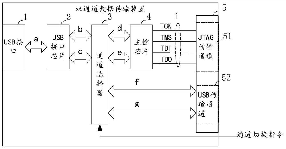
[0031] Such as figure 1 As shown, this embodiment provides a dual-channel data transmission device, including:

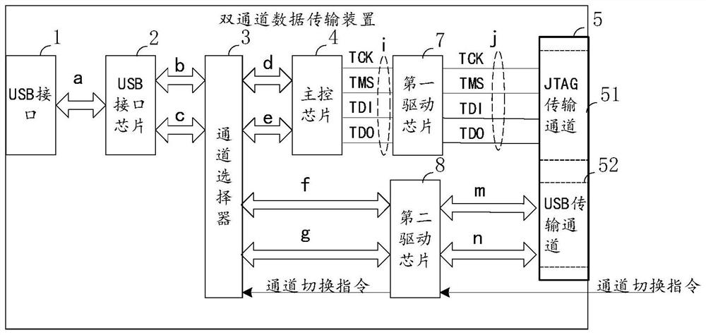
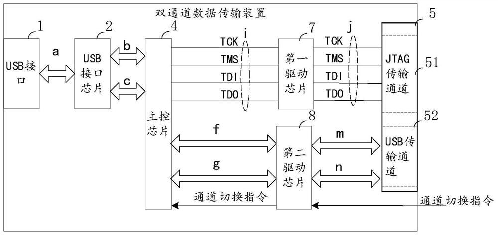
[0032] USB interface 1, USB interface chip 2, channel selector 3, main control chip 4 with USB protocol and JTAG protocol conversion function, data transmission interface 5 with JTAG transmission channel and USB transmission channel, wherein,

[0033] The USB interface 1, the USB interface chip 2, the channel selector 3, the main control chip 4 and the JTAG transmission channel 51 form a first data transmission channel, and the first data transmission channel is used to transmit Configuration information, the configuration information here includes the information used for the initial configuration of the programmable logic device transmitted by the host computer to the programmable logic device through a dual-channel data transmission device, and also includes The information transmitted by the channel data transmission device to the upper computer;

[0034] The ...

Embodiment 2

[0072] Such as Figure 4 As shown, this embodiment provides a dual-channel data transmission system, including:

[0073] The upper computer 9, the programmable logic device 10 and the dual-channel data transmission device as in any one of the first embodiment, wherein,

[0074]The dual-channel data transmission device is connected to the host computer 9 through the USB interface 1 for transmitting the configuration information or the user information;

[0075] The programmable logic device 10 includes a user interface 11 and a configuration interface 12, the configuration interface 12 is correspondingly connected to the JTAG transmission channel 51, and is used to transmit the configuration information, and the user interface 11 is connected to the USB transmission channel 52 corresponding to the connection, used to transmit the user information;

[0076] The channel selector 3 is connected to the user interface 11 for receiving the channel switching instruction sent by the ...


PUM


Abstract

The invention discloses a dual-channel data transmission device. The device comprises a USB interface, a USB interface chip, a channel selector, a main control chip with a USB protocol and JTAG protocol conversion function, and a data transmission interface with a JTAG transmission channel and a USB transmission channel, the USB interface, the USB interface chip, the channel selector, the main control chip and the JTAG transmission channel form a first data transmission channel, and the first data transmission channel is used for transmitting configuration information; the USB interface, the USB interface chip, the channel selector, the main control chip and the USB transmission channel form a second data transmission channel, and the second data transmission channel is used for transmitting user information; and the channel selector is used for acquiring the channel switching instruction and switching from the first data transmission channel to the second data transmission channel fordata transmission under the control of the channel switching instruction. According to the invention, the technical problem of single function of the downloading line architecture of the USB-to-JTAGprotocol at present is solved.

Description

technical field [0001] The invention relates to the technical field of data transmission, in particular to a dual-channel data transmission device and system. Background technique [0002] In the development and application of programmable logic devices such as FPGA and CPLD, the download cable (also called download cable) based on the USB to JTAG protocol (IEEE1149.1 Test Access Port) is a commonly used debugging tool. The development direction of the existing download line architecture is to achieve better compatibility in order to support more types of programmable logic devices. [0003] However, in the process of realizing the technical solution of the invention in the embodiment of the present application, the inventor of the present application found that the above-mentioned technology has at least the following technical problems: [0004] The download line architecture of the current USB-to-JTAG protocol has a single function, and it is idle after the download of t...

Claims


Application Information

Patent Timeline
IPC IPC(8): G06F13/38
CPCG06F13/385G06F2213/3812
Inventor 谢元禄刘璟张君宇霍长兴呼红阳张坤刘明
Owner INST OF MICROELECTRONICS CHINESE ACAD OF SCI
Learn More