
Flue gas waste heat recycling device for reverse use of cooling tower and working method of flue gas waste heat recycling device

A flue gas waste heat and working method technology, applied in heat recovery systems, water shower coolers, energy-saving heating/cooling, etc., can solve problems such as waste of flue gas waste heat, atmospheric environment impact, and short use time, so as to avoid idleness , Reduce pollution and reduce energy waste

Pending Publication Date: 2022-08-02
CECEP CHANGZHOU INST FOR ENERGY SAVING
View PDF0 Cites 0 Cited by
  • Summary
  • Abstract
  • Description
  • Claims
  • Application Information

AI Technical Summary

Problems solved by technology

[0004] 1. The "chiller + cooling tower" is not used for a long time throughout the year, and it only provides cooling for buildings in summer. In winter, if the existing cooling tower is used for heating, the water supply temperature of the cooling tower to the evaporator should be above 12 °C , then the cooling tower must absorb heat from the atmosphere, and the atmospheric temperature must be above 15°C, which is impossible in most areas. In winter, the "chiller + cooling tower" does not participate in building heating, resulting in idle equipment ;
[0005] 2. Gas-fired boilers will produce a large amount of high-temperature flue gas during the combustion process, but they are often discharged directly to the atmosphere without heat exchange treatment, which not only wastes a lot of waste heat of the flue gas, but also has a certain impact on the atmospheric environment

Method used


Image

  • Flue gas waste heat recycling device for reverse use of cooling tower and working method of flue gas waste heat recycling device
  • Flue gas waste heat recycling device for reverse use of cooling tower and working method of flue gas waste heat recycling device
  • Flue gas waste heat recycling device for reverse use of cooling tower and working method of flue gas waste heat recycling device

Examples


Embodiment Construction

[0033] In order to make the purposes, technical solutions and advantages of the embodiments of the present invention clearer, the technical solutions of the present invention will be clearly and completely described below with reference to the accompanying drawings. Obviously, the described embodiments are part of the embodiments of the present invention, not all of them. example. Based on the embodiments of the present invention, all other embodiments obtained by those of ordinary skill in the art without creative efforts shall fall within the protection scope of the present invention.

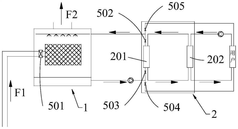
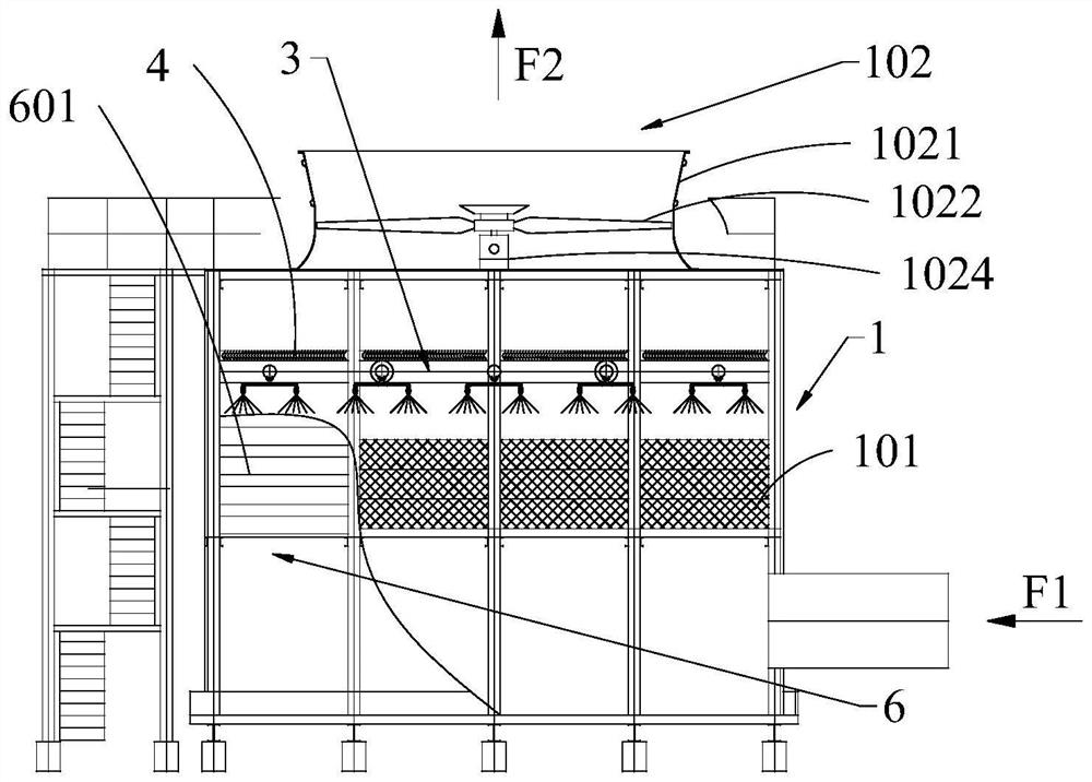
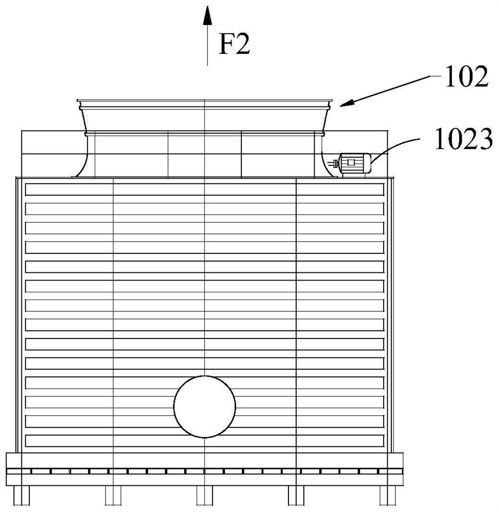
[0034] like figure 1 , figure 2 and Figure 5 As shown, this embodiment provides a flue gas waste heat recovery and utilization device for reverse use of a cooling tower, including:

[0035] Cooling tower 1 and heat pump unit 2; wherein the cooling tower 1 is provided with a flue gas inlet at the lower part of the filler 101; during heating, the water distribution system 3 in the cooling ...


PUM


Abstract

The invention belongs to the technical field of flue gas waste heat recycling, and particularly relates to a flue gas waste heat recycling device for reverse use of a cooling tower and a working method of the flue gas waste heat recycling device. A flue gas leading-in opening is formed in the cooling tower and is positioned at the lower part of the filler; during heating, a water distribution system in the cooling tower is used for introducing water from an evaporator of the heat pump unit; a shutter opening and closing mechanism in the cooling tower controls shutters to be closed, so that a heat source space is formed below the filler after smoke is guided in; according to the flue gas waste heat recycling device for reverse use of the cooling tower and the working method of the flue gas waste heat recycling device for reverse use of the cooling tower, dual purposes of the cooling tower are achieved, idling of equipment is avoided, waste heat of boiler flue gas is recycled, and the waste heat recycling device for reverse use of the cooling tower and the working method of the flue gas waste heat recycling device for reverse use of the cooling tower have the advantages of being energy-saving and environment-friendly. The waste of energy is reduced, and the pollution of flue gas to the environment is reduced.

Description

technical field [0001] The invention belongs to the technical field of flue gas waste heat recovery and utilization, and particularly relates to a flue gas waste heat recovery and utilization device for reverse use of a cooling tower and a working method thereof. Background technique [0002] At present, in the traditional building energy supply system, gas boilers are used for heating in winter, and "chillers + cooling towers" are used for cooling in summer. [0003] But for this system, there are still the following defects: [0004] 1. The "chiller unit + cooling tower" is not used for a long time throughout the year. It only provides cooling for the building in summer. In winter, if the existing cooling tower is used for heating, the temperature of the water supply from the cooling tower to the evaporator should be above 12 °C , then the cooling tower needs to absorb heat into the atmosphere, and the atmospheric temperature must be above 15 °C, which is impossible in mo...

Claims


Application Information

Patent Timeline
IPC IPC(8): F23J15/06F28C1/02F28F25/08F28F25/10F28F27/00
CPCF23J15/06F28C1/02F28F25/08F28F25/10F28F27/003Y02E20/30
Inventor 杜玉吉王红张林兵张晔
Owner CECEP CHANGZHOU INST FOR ENERGY SAVING
Learn More