Iron core winding clamping and rotating mechanism for transformer production and method thereof

A technology for clamping and rotating bobbins, used in inductor/transformer/magnet manufacturing, coil manufacturing, electrical components, etc., and can solve problems such as poor clamping effect of iron core bobbins

Inactive Publication Date: 2020-09-11
何国标
View PDF0 Cites 2 Cited by
  • Summary
  • Abstract
  • Description
  • Claims
  • Application Information

AI Technical Summary

Problems solved by technology

[0005] The object of the present invention is to solve the above-mentioned problem of poor clamping effect of the existing iron core winding frame, and provide a core winding frame clamping and rotating mechanism for transformer production, which is convenient for the front and rear of the iron core winding frame. The end clamping limit improves the stability during the rotation process, the support stability is improved through the support module, and the rotation consistency and rotation efficiency are improved through an iron core winding frame rotation drive motor, thereby further improving the overall winding effect

Method used


Image

  • Iron core winding clamping and rotating mechanism for transformer production and method thereof
  • Iron core winding clamping and rotating mechanism for transformer production and method thereof
  • Iron core winding clamping and rotating mechanism for transformer production and method thereof

Examples


Embodiment Construction

[0026] The specific implementation manner of the present invention will be described in detail below in conjunction with the accompanying drawings.

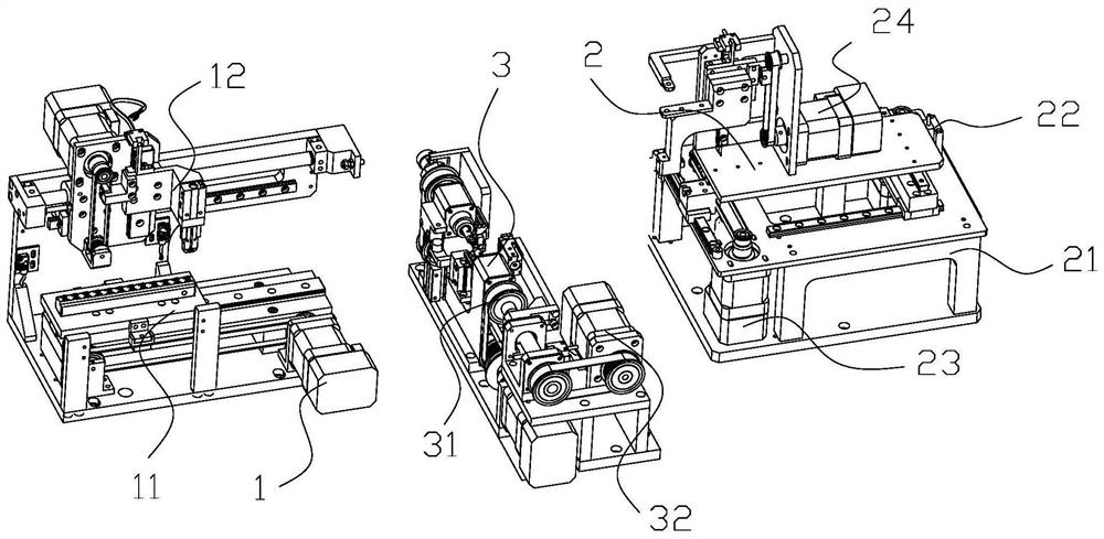
[0027] like figure 1 As shown, a transformer production equipment includes a frame and an iron core winding frame conveying device 1 on it, a coil conveying device 2 clamping winding device 3 and a coil cutting device; the clamping winding device 3 is located at the core winding Between the wire frame conveying device 1 and the coil conveying device 2; the iron core winding frame conveying device 1 is used to convey the iron core winding frame to the clamping winding device 3, and the coil conveying device 2 is used to convey the coil to the clamp On the tight winding device 3, the clamping winding device 3 is used to wind the coil onto the iron core winding frame, and the coil cutting device is used to cut the coil after the iron core winding frame winds the coil.

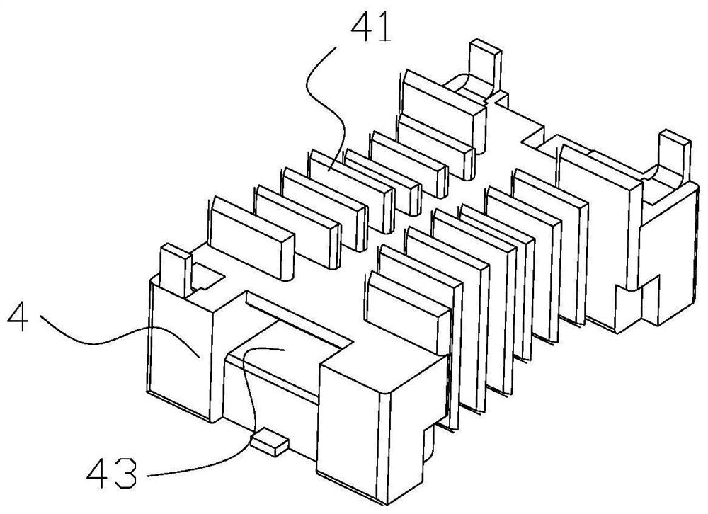
[0028] like figure 2As shown in the figure, the product iron...


PUM


Abstract

The invention belongs to the technical field of transformer production. The invention discloses an iron core winding frame clamping and rotating mechanism for transformer production. The iron core winding frame clamping and rotating mechanism comprises an iron core winding frame clamping bottom plate, an iron core winding frame rotating U-shaped frame, an iron core winding frame rotating driving motor, an iron core winding frame rotating driving rotating shaft, a first rotating module, a second rotating module and a supporting module. The iron core winding frame clamping bottom plate is arranged on a rack; the iron core winding frame rotating U-shaped frame is arranged on the iron core winding frame clamping bottom plate; the iron core winding frame rotating driving motor is arranged on the iron core winding frame clamping bottom plate, the winding frame rotating driving rotating shaft is connected with the iron core winding frame rotating driving motor, the first rotating module and the second rotating module are arranged at the two ends of the winding frame rotating driving rotating shaft respectively, and the supporting module is arranged at a notch of the iron core winding frame rotating U-shaped frame. The iron core winding frame clamping and rotating mechanism has the advantages that the clamping firmness of the iron core winding frame is improved, the stability of the iron core winding frame in the winding process is improved, and the winding efficiency and the winding precision of the iron core winding frame are enahnced.

Description

technical field [0001] The invention belongs to the technical field of transformer production, and in particular relates to an iron core bobbin frame clamping and rotating mechanism for transformer production and a method thereof. Background technique [0002] Transformers generally include iron core winding frame, iron core and coil. Iron core winding frame is also called transformer skeleton. Transformer skeleton is the main structural part of transformer, which provides winding space for copper wire in transformer and fixes iron in transformer The core; the middle part of the core winding frame is provided with a core slot, and the outer ring of the core winding frame is provided with a plurality of winding spacers, the iron core is installed in the core slot of the core winding frame, and the coil is wound Between two adjacent winding spacers on the core winding frame. During production, the empty core winding frame is first transferred to the coil winding place, then t...

Claims


Application Information

Patent Timeline
Patent Type & Authority Applications(China)
IPC IPC(8): H01F41/06H01F41/098H01F41/096H01F41/09H01F41/082
CPCH01F41/06H01F41/082H01F41/09H01F41/096H01F41/098
Inventor 何国标王德胜杨道济
Owner 何国标
Why Eureka
Try Eureka