
Camera device, control method and electronic device

A camera device and control element technology, applied in the field of communication, can solve the problems of high noise, insufficient thrust, large volume, etc., and achieve the effect of low noise and large volume

Active Publication Date: 2022-04-22
VIVO MOBILE COMM CO LTD
View PDF6 Cites 0 Cited by
  • Summary
  • Abstract
  • Description
  • Claims
  • Application Information

AI Technical Summary

Problems solved by technology

[0003] The embodiment of the present application provides a device state detection method and an electronic device, which can solve the problems of insufficient thrust, large volume and high noise of the camera device in the prior art

Method used


Image

  • Camera device, control method and electronic device
  • Camera device, control method and electronic device
  • Camera device, control method and electronic device

Examples


Embodiment Construction

[0029] The following will clearly and completely describe the technical solutions in the embodiments of the present application with reference to the drawings in the embodiments of the present application. Obviously, the described embodiments are part of the embodiments of the present application, not all of them. Based on the embodiments in this application, all other embodiments obtained by persons of ordinary skill in the art without creative efforts fall within the protection scope of this application.

[0030] The terms "first", "second" and the like in the specification and claims of the present application are used to distinguish similar objects, and are not used to describe a specific sequence or sequence. It is to be understood that the data so used are interchangeable under appropriate circumstances such that the embodiments of the application can be practiced in sequences other than those illustrated or described herein. In addition, "and / or" in the specification an...


PUM


Abstract

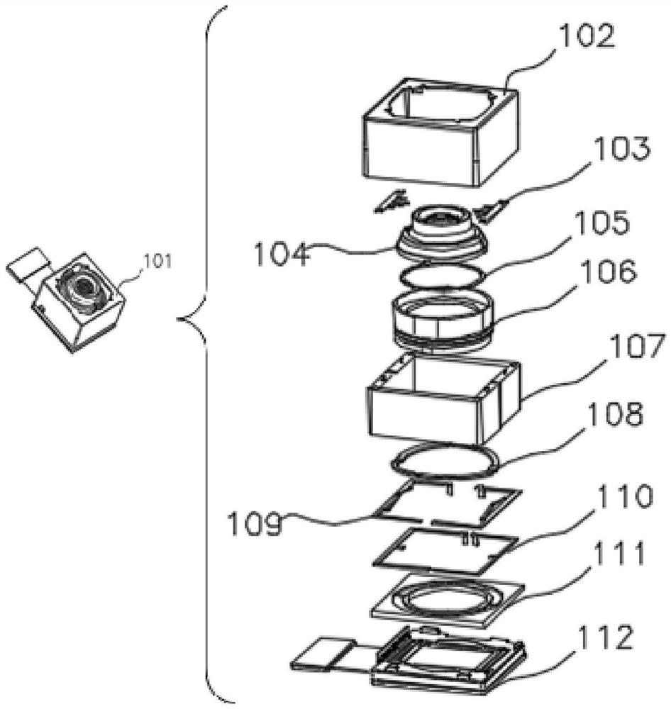
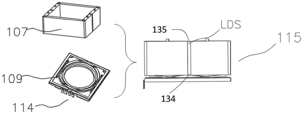
The application discloses an imaging device, a control method and electronic equipment, and relates to the technical field of communication. The imaging device includes: including: a circuit board; a photosensitive chip module, the photosensitive chip module is installed on the circuit board, and the photosensitive chip module is electrically connected to the circuit board; a first lens module, the The first lens module is located on the side of the photosensitive chip module away from the circuit board, the first lens module is connected to the circuit board through a first driver, and the first lens module is opposite to the The photosensitive chip module is movable in a direction close to or away from the photosensitive chip module; the second lens module, the second lens module is connected to the first lens module through a second driving member, The second lens module is movable relative to the first lens module in a direction approaching or away from the photosensitive chip module. The invention can solve the problems of insufficient thrust, large volume and high noise of the camera device existing in the prior art.

Description

technical field [0001] Embodiments of the present invention relate to the field of communication technologies, and in particular, to an imaging device, a control method, and electronic equipment. Background technique [0002] In related technologies, a single voice coil motor is usually used to drive a lens or a multi-voice coil motor to separately drive multiple lens modules for focusing. The structure of the voice coil motor is complex, and the thrust of the small-sized motor in the direction of the main optical axis is insufficient and the imaging quality is not high; In order to obtain a larger thrust, the volume of the motor needs to be enlarged. The large-volume motor will increase the vibration and noise, and it is in contradiction with the demand for small-volume devices on the equipment. Contents of the invention [0003] Embodiments of the present application provide a device state detection method and an electronic device, which can solve the problems of insuffi...

Claims


Application Information

Patent Timeline
Patent Type & Authority Patents(China)
IPC IPC(8): H04N5/225H04N5/232
CPCH04N23/55H04N23/51H04N23/54H04N23/60
Inventor 陈学银
Owner VIVO MOBILE COMM CO LTD
Learn More