Reversed-field permanent-magnet focusing system for multi-beam millimeter wave traveling-wave tubes and manufacturing method thereof

A permanent magnet focusing and millimeter wave technology, which is used in the manufacture of discharge tubes, non-light-emitting electrodes, and transit time electron tubes, etc. problems, to achieve the effect of high practical value

Inactive Publication Date: 2011-01-12
HUADONG PHOTOELECTRIC TECHN INST OF ANHUI PROVINCE
View PDF4 Cites 22 Cited by
  • Summary
  • Abstract
  • Description
  • Claims
  • Application Information

AI Technical Summary

Problems solved by technology

However, the disadvantage of this magnetic system is that the volume of the permanent magnet in the permanent magnet focusing system becomes very large with the increase of the length of the slow wave system of the traveling wave tube, which is not conducive to the miniaturization of the traveling wave tube
The length of the TWT slow-wave system depends on the gain of the tube design, so it is generally not suitable to use this permanent magnet focusing system when the gain of the millimeter-wave multi-beam TWT exceeds 40dB.

Method used


Image

  • Reversed-field permanent-magnet focusing system for multi-beam millimeter wave traveling-wave tubes and manufacturing method thereof
  • Reversed-field permanent-magnet focusing system for multi-beam millimeter wave traveling-wave tubes and manufacturing method thereof
  • Reversed-field permanent-magnet focusing system for multi-beam millimeter wave traveling-wave tubes and manufacturing method thereof

Examples


Embodiment Construction

[0045] Below with reference to the accompanying drawings, through the description of the embodiments, the specific implementation of the present invention, such as the mutual positional relationship and working principle between the various components involved, etc., will be further described in detail, so as to help those skilled in the art to understand the invention Have a more complete, accurate and in-depth understanding of the concept and technical solutions of the company.

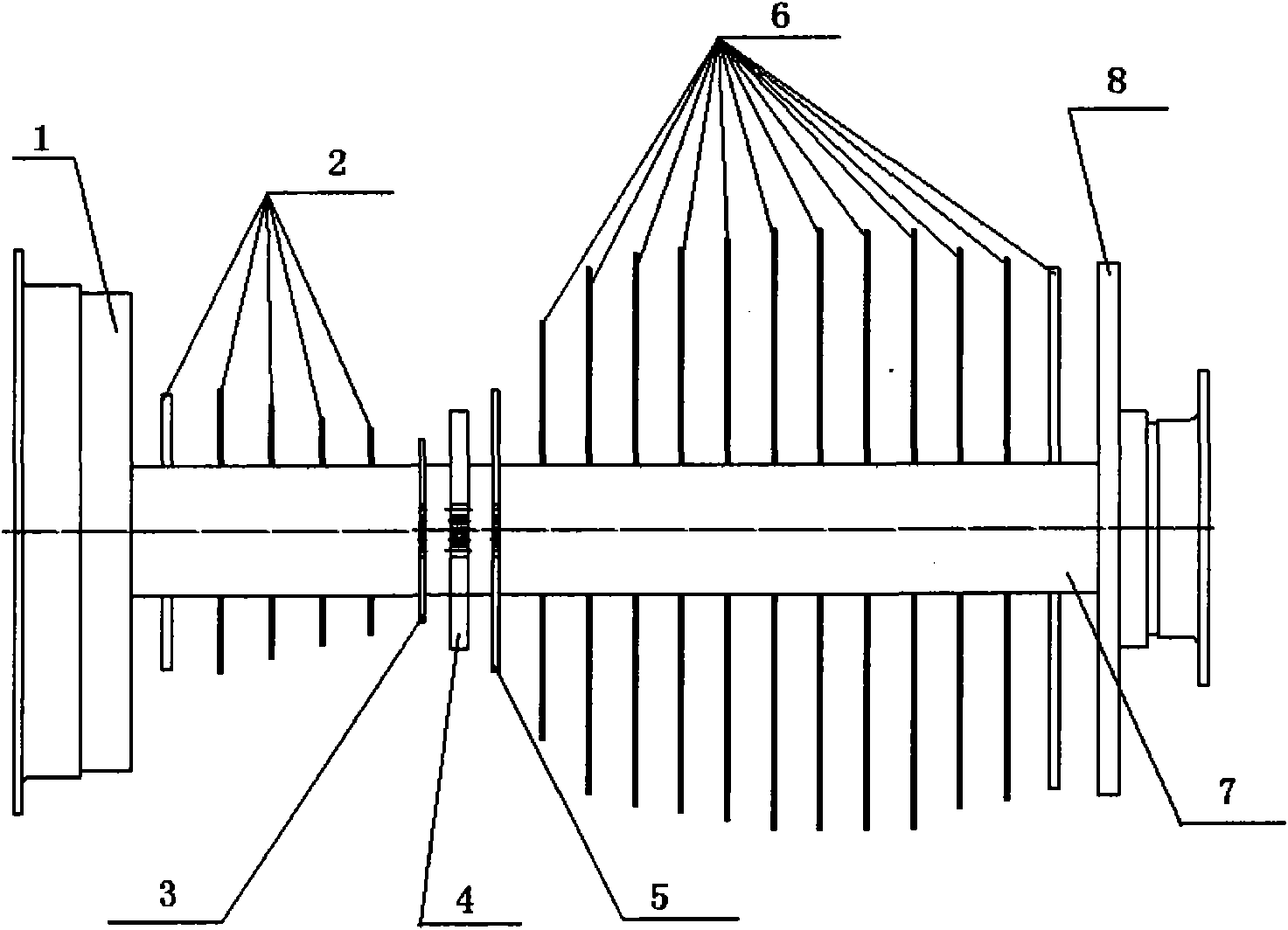
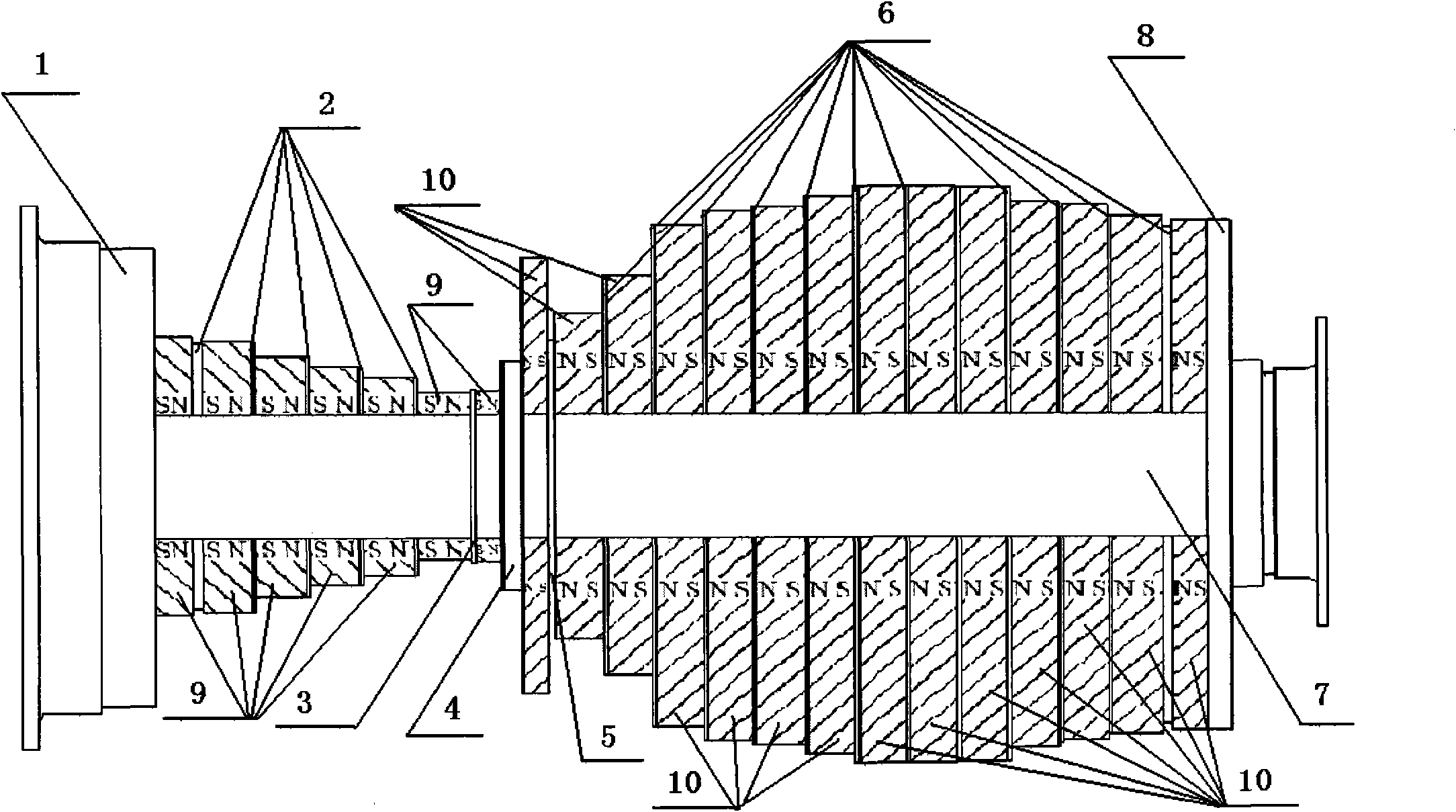
[0046] Such as figure 1 , figure 2The millimeter-wave multi-beam traveling wave tube inverted field permanent magnet focusing system includes an electron gun end cover 1, a first magnetic field rectifier 2, a first spike generating pole piece 3, a magnetic field reverse pole piece 4, and a second spike generating pole The shoe 5, the second magnetic field rectifier 6, the vacuum-sealed shell 7, the collector terminal cover 8, the first permanent magnet 9, and the second permanent magnet 10 constit...


PUM


Abstract

The invention discloses a reversed-field permanent-magnet focusing system for multi-beam millimeter wave traveling-wave tubes, which consists of an electron gun end face (1), first magnetic field rectifiers (2), a first peak generation pole shoe (3), a magnetic field reversal pole shoe (4), a second peak generation pole shoe (5), second magnetic field rectifiers (6), a vacuum sealed case (7), a collector end face (8), first permanent magnets (9) and second permanent magnets (10). The reversed-field permanent-magnet focusing system for the multi-beam millimeter wave traveling-wave tubes rectifies magnetic fields on the left and right sides of a magnetic system by the first and second magnetic field rectifiers (2 and 6) so as to reduce a transverse magnetic field without influencing flux rates of electron beams, and simultaneously solves the problem of large volumes of the permanent magnets of a uniform-field permanent-magnet focusing system with large gain due to the applicability of the plurality of first and second permanent magnets (9 and 10) with small volumes to the focusing system.

Description

technical field [0001] The invention belongs to the field of microwave vacuum electronics, and in particular relates to a millimeter wave multi-beam traveling wave tube reverse field permanent magnet focusing system and a manufacturing method thereof. Background technique [0002] As a vacuum microwave power amplifier, traveling wave tubes have the advantages of wide frequency band, large gain, high efficiency, and large output power. They are widely used in various civil and military microwave transmitters. [0003] With the gradual crowding of centimeter-wave multi-beam traveling wave tube users, the research and development of millimeter-wave multi-beam traveling wave tube technology has attracted attention for many years. Due to the "commensurability" between the size of conventional microwave devices and the working wavelength, for the design and manufacture of millimeter-wave multi-beam traveling wave tubes, the millimeter-wave multi-beam The radial size of the travel...

Claims


Application Information

Patent Timeline
Patent Type & Authority Applications(China)
IPC IPC(8): H01J23/087H01J9/14
Inventor 吴华夏江祝苗方卫余峰张丽
Owner HUADONG PHOTOELECTRIC TECHN INST OF ANHUI PROVINCE
Why Eureka
Try Eureka