
Street lamp brightness monitoring method for street lamp system

A street lamp and brightness technology, which is applied in the direction of energy-saving control technology, electrical components, etc., can solve the problems that the brightness adjustment of street lamps cannot be realized, the consumption reduction and energy saving cannot be realized, and the switching function cannot be performed, so as to improve utilization efficiency and control accuracy, improve Reduce consumption and save energy, and ensure the effect of lighting requirements

Inactive Publication Date: 2020-09-11
四川艾贝斯科技发展有限公司
View PDF8 Cites 6 Cited by
  • Summary
  • Abstract
  • Description
  • Claims
  • Application Information

AI Technical Summary

Problems solved by technology

[0005] In the above patent application, although the light sensor unit collects the illuminance of the area where the street lamp is located and uses it as the basis for controlling the street light switch, which solves the demand for emergency lighting to a certain extent, it cannot realize the brightness adjustment of the street lamp according to the ambient light intensity. In addition, in the process of controlling the street lamp control module in the server control system, only one-way communication control is used, and there is a situation of control failure, such as communication failure, even if the server control system sends a signal to the street lamp control module. The module sends a control signal to turn on or off, but the street light control module may not receive the signal and cannot perform the switch function, which will lead to control failure

Method used


Image

  • Street lamp brightness monitoring method for street lamp system
  • Street lamp brightness monitoring method for street lamp system
  • Street lamp brightness monitoring method for street lamp system

Examples


Embodiment

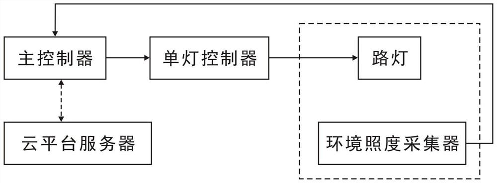
[0033] like figure 1 As shown, the street lamp system of the present invention includes a cloud platform server, a main controller, a single lamp controller, a street lamp and an ambient illumination collector, the cloud platform server is connected to the main controller by wireless communication, and the main controller The control signal output end of the controller is connected to the control signal input end of the single lamp controller, and the output end of the single lamp controller is connected to the power input end of the street lamp, which is used to collect the illuminance of the area where the street lamp is located. The signal output terminal of the ambient illumination collector is connected to the signal input terminal of the main controller; at the same time, the power input terminal of the single lamp controller is connected to a contactor, and the contactor is correspondingly connected to the main controller at the same time ;

[0034] The street lamp brigh...


PUM


Abstract

The invention discloses a street lamp brightness monitoring method for a street lamp system. The street lamp brightness monitoring method comprises the following steps: an environment illumination collector collects illumination information of an area where a street lamp is located and sends the illumination information to a main controller; the main controller calculates to obtain an average illuminance value; the main controller sets a preset minimum illuminance threshold value and a preset maximum illuminance threshold value and compares the preset minimum illuminance threshold value and the preset maximum illuminance threshold value with the actual average illuminance value of the area where the street lamp is located, and then the on-off state of the street lamp of the single-lamp controller is controlled according to the actual average illuminance values; and the main controller sets a correction illuminance value and a standard illuminance value, calculates the difference between the actual average illuminance value and the standard illuminance value of the area where the street lamp is located, compares the difference with the correction illuminance value, and adjusts the brightness of the street lamp according to the difference and the correction illuminance value. The problem of frequently switching on and off the street lamp is avoided, a closed-loop monitoring process is formed, full-automatic brightness adjustment of the street lamp is realized, the consumption reduction and energy saving effects are significantly improved, and environmental protection is facilitated.

Description

technical field [0001] The invention relates to a brightness monitoring method, in particular to a street lamp brightness monitoring method used in a street lamp system. Background technique [0002] As an important part of municipal engineering, urban street lamps are getting more and more attention from the government, and their precise control and energy saving are becoming more and more important. Street light system is the abbreviation of urban municipal street lighting system. The existing street light system has become more and more intelligent, generally including cloud platform server, main controller and single light controller, wireless communication between cloud platform server and main controller Connection to achieve centralized remote control, wired or wireless communication connection between the main controller and the single lamp controller, to realize the independent control of the single lamp controller by the main controller, and the single lamp control...

Claims


Application Information

Patent Timeline
Patent Type & Authority Applications(China)
IPC IPC(8): H05B47/165
CPCH05B47/165Y02B20/40
Inventor 罗仁强何勇
Owner 四川艾贝斯科技发展有限公司
Learn More