Medical protective clothing

A technology for protective clothing and medical use, applied in the field of protective clothing, can solve the problems of poor air permeability and poor airtight performance of protective clothing

Active Publication Date: 2020-09-15
HENAN YADU IND
View PDF4 Cites 0 Cited by
  • Summary
  • Abstract
  • Description
  • Claims
  • Application Information

AI Technical Summary

Problems solved by technology

[0005] In view of the above situation, in order to overcome the defects of the prior art, the present invention provides a protective clothing for medical use, which effectively solves the problems of poor air permeability and poor airtight performance of the protective clothing in the prior art

Method used


Image

  • Medical protective clothing
  • Medical protective clothing
  • Medical protective clothing

Examples


Embodiment 1

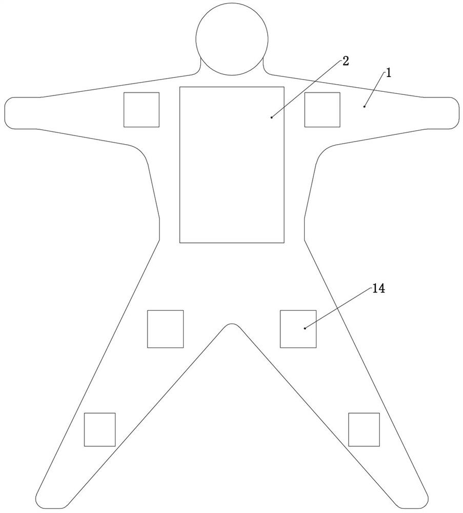
[0040]Embodiment 1, the present invention is a kind of protective clothing for medical use, including protective clothing 1, described protective clothing 1 is a common protective clothing 1, which can provide a fixed foundation for subsequent structures, and the protective clothing 1 adopted in the present invention is preferably a zipper The protective clothing 1 on the chest is convenient for subsequent arrangement on the back of the protective clothing 1 and does not interfere with the normal putting on and taking off of the protective clothing 1. It is characterized in that the back of the protective clothing 1 is detachably connected with a box body 2, and its thickness is about 10 centimeters, about 60 centimeters in height, the box body 2 is provided with an upper warehouse 3, a middle warehouse 4, and a lower warehouse 5. The three warehouses are separated by two partitions fixedly connected to the inside of the box body 2. Bins are adjacent in turn, refer to Figure ...

Embodiment 2

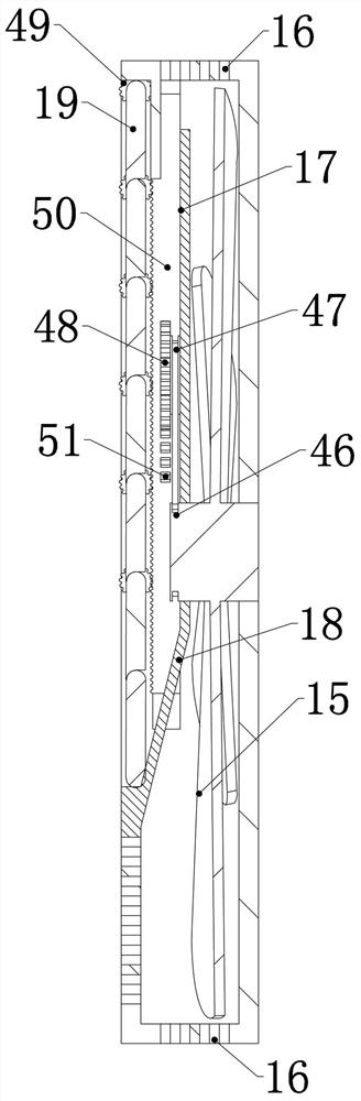
[0043] Embodiment 2, on the basis of Embodiment 1, the middle chamber 4 is fixedly connected with a cooling chamber 20, and the cooling chamber 20 is used to store a solid cooling agent, which can be dry ice, ice or other common fixed cooling The cooling chamber 20 is connected to the middle chamber 4 and a switch of the cooling chamber 20 is arranged at the connecting place. After the switch of the cooling chamber 20 is opened, the cooling chamber 20 is opened, and the solid cooling agent in the cooling chamber 20 can cool the air passing through the middle chamber 4. Perform cooling treatment to ensure the coolness of the air in the protective clothing 1. It should be noted that the walls of the cooling chamber 20 are inlaid with insulation partitions to ensure that the cold air of the refrigerant will not disperse to the outside.

Embodiment 3

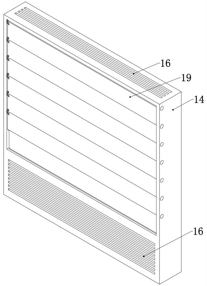
[0044] Embodiment 3, on the basis of Embodiment 2, the switch of the middle chamber 4 and the switch of the cooling chamber 20 are solenoid valves, the inner louvers 12, the outer louvers 13, and the diversion louvers 19 are all electric louvers. The air treatment structure is a miniature air cleaner, which can be a CGJ-AW2-06 type air cleaner, or other common miniature air cleaners, the two exhaust fans 8, the air treatment structure, a plurality of The circulation fan blade 15 and a plurality of the electric louvers are electrically connected to the control module, the control module includes a control unit and a timing unit, and the control logic is pre-programmed in the control unit, so The control logic described is divided into the following three steps:

[0045] Step 1: Turn on the middle compartment 4 switch, inner louver 12, exhaust fan 8, air treatment structure, and cooling compartment 20, and close the circulation fan blade 15, circulation louver, and outer louver ...


PUM


Abstract

The invention relates to medical protective clothing. The problem that protective clothing in the prior art is poor in air permeability is effectively solved. According to the technical scheme, the protective clothing comprises a protective clothing body, the back of the protective clothing body is detachably connected with a box body, an upper bin, a middle bin and a lower bin are arranged in thebox body, outer air inlets are formed in two side walls of the upper bin, baffles are arranged beside the outer air inlets, an air treatment structure is arranged between the two baffles, a draught fan is arranged on the upper bin, the middle bin is provided with an inner air inlet, a middle bin switch is arranged beside the inner air inlet, an inner air outlet is formed in the side wall of the lower bin, an outer air outlet is formed in the side wall of the lower bin, an inner shutter and an outer shutter are arranged beside the inner air outlet and the outer air outlet, a control module connected with the middle bin switch, the inner shutter and the outer shutter is arranged in the middle bin, and the control module controls the middle bin switch and the inner shutter to synchronously switch and the outer shutter to be closed when the inner shutter is opened. The medical protective clothing is simple in structure, exchange and circulation of air inside the protective clothing and outside air can be efficiently and safely achieved, meanwhile, incoming air can be sterilized, and the practicability is high.

Description

technical field [0001] The invention relates to the technical field of protective clothing, in particular to a medical protective clothing. Background technique [0002] Medical protective clothing is protective clothing for medical staff, used to isolate germs, harmful ultrafine dust, acidic solutions, saline solutions, etc. in the medical environment. Strong mechanical properties, soft and comfortable texture. Medical protective clothing is generally made of PP non-woven material, which has the characteristics of soft texture, anti-static, and better impermeability. The above materials are all materials with poor air permeability. Long-term wearing will cause medical staff to sweat more, resulting in a large loss of physical strength, and because it takes too long to wear protective clothing, most medical staff will not drink water while wearing protective clothing. This causes the medical staff to sweat a lot but not get water supplement, which can easily lead to fatigu...

Claims


Application Information

Patent Timeline
Patent Type & Authority Applications(China)
IPC IPC(8): A41D13/002A61L9/20A61L9/14
CPCA41D13/0025A61L9/20A61L9/14A61L2209/134
Inventor 韩立涛韩涵段书霞佘开江朱政辉付迎坤韩修恒陈琳潘洪福林建香段晓堂赵欣王蓉徐玉茵范頔闫钧高文静张丹丹陈玮雯柳小军田林奇周静崔彬彬魏峥琦李夏
Owner HENAN YADU IND
Why Eureka
Try Eureka