Cutting device for stainless steel filter screen processing

A technology of cutting device and filter screen, which is applied in the direction of metal processing equipment, etc., can solve the problems of single cutting direction of the cutter, inability to cut the filter screen, inconvenient clamping and fixing of the filter screen, etc., and achieve the effect of improving flexibility

Active Publication Date: 2020-09-15
瑞安市邵伟五金经营部
View PDF10 Cites 2 Cited by
  • Summary
  • Abstract
  • Description
  • Claims
  • Application Information

AI Technical Summary

Problems solved by technology

However, the above-mentioned technical solution has a relatively single cutting direction of the cutting knife in actual use, and cannot flexibly

Method used


Image

  • Cutting device for stainless steel filter screen processing
  • Cutting device for stainless steel filter screen processing
  • Cutting device for stainless steel filter screen processing

Examples


Embodiment 1

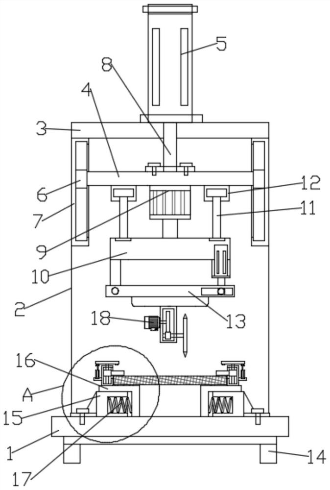
[0026] Such as figure 1 As shown, in the embodiment provided by the present invention, a cutting device for stainless steel filter mesh processing includes a base 1, the four corners of the lower surface of the base 1 are provided with feet 14; the base 1 is provided with clips The clamping mechanism is used to clamp and fix the stainless steel filter screen 29; the upper surface of the rear side of the base 1 is also fixedly provided with a supporting backboard 2, and the top of the supporting backboard 2 is provided with a supporting top board 3, The support top plate 3 is provided with a hydraulic telescopic cylinder 5, and the telescopic end of the hydraulic telescopic cylinder 5 is linked with a piston rod 8, and the bottom end of the piston rod 8 is fixedly installed with a lifting beam 4, and a useful In order to adjust the first driving motor 9 of the horizontal rotation direction of the cutting assembly, the output shaft of the first driving motor 9 is equipped with a...

Embodiment 2

[0032] Such as figure 1 As shown, in the embodiment provided by the present invention, a cutting device for stainless steel filter mesh processing includes a base 1, the four corners of the lower surface of the base 1 are provided with feet 14; the base 1 is provided with clips The clamping mechanism is used to clamp and fix the stainless steel filter screen 29; the upper surface of the rear side of the base 1 is also fixedly provided with a supporting backboard 2, and the top of the supporting backboard 2 is provided with a supporting top board 3, The support top plate 3 is provided with a hydraulic telescopic cylinder 5, and the telescopic end of the hydraulic telescopic cylinder 5 is linked with a piston rod 8, and the bottom end of the piston rod 8 is fixedly installed with a lifting beam 4, and a useful In order to adjust the first driving motor 9 of the horizontal rotation direction of the cutting assembly, the output shaft of the first driving motor 9 is equipped with a...


PUM


Abstract

The invention relates to the field of stainless steel filter screen processing equipment and in particular discloses a cutting device for stainless steel filter screen processing. The cutting device comprises a base, wherein a clamping mechanism is arranged on the base and is used for clamping and fixing a stainless steel filter screen; a supporting back plate is further fixedly arranged on the upper surface of the back side of the base, a supporting top late is arranged at the top end of the supporting back plate, a hydraulic telescopic cylinder is arranged on the supporting top plate, a piston rod is arranged at a telescopic end of the hydraulic telescopic cylinder in a linking manner, a lifting cross beam is fixedly mounted at the bottom end of the piston rod, and a first driving motorfor adjusting the horizontal rotating direction of a cutting assembly is arranged on the lifting cross beam. The cutting device provided by the embodiment of the invention can cut the stainless steelfilter screen, and is matched with a vertical adjusting assembly and the first driving motor to further adjust the horizontal position and the vertical angle of the cutting assembly, so that the cutting flexibility of the cutting assembly on the stainless steel filter screen is improved.

Description

technical field [0001] The invention relates to the field of stainless steel filter net processing equipment, in particular to a cutting device for stainless steel filter net processing. Background technique [0002] The stainless steel filter screen is generally a multi-layer structure, usually a layer of non-woven fabric in the middle, and the upper and lower layers are mesh metal filter screens. Several layers of materials are extruded and bonded together, and after rolling forming, they are generally corrugated. Cut off into a certain length of filter screen according to actual needs. [0003] At present, the stainless steel filter mesh needs to be cut by a cutting device to obtain a product that meets the size. [0004] In the Chinese patent whose authorized notification number is CN 209599277U, a filter screen cutter with a diamond cutter is disclosed, including a base, a cutting plate, a cutting knife, a side plate and a connecting plate, the side plate is fixedly ar...

Claims


Application Information

Patent Timeline
IPC IPC(8): B21F33/00
CPCB21F33/005
Inventor 不公告发明人
Owner 瑞安市邵伟五金经营部
Why Eureka
Try Eureka