Multipurpose milling clamp

A fixture and bottom plate technology, applied in the direction of clamping, manufacturing tools, supports, etc., can solve the problems of reducing the production efficiency of the oil separator, high fixture manufacturing costs, high fixture management costs, etc., to achieve low fixture management costs, low production costs, The effect of reducing production cost and management cost

Inactive Publication Date: 2020-09-15
AVIC LIYUAN HYDRAULIC
View PDF12 Cites 1 Cited by
  • Summary
  • Abstract
  • Description
  • Claims
  • Application Information

AI Technical Summary

Problems solved by technology

The oil separator is a mass-produced product. Generally, there are many stations for processing the oil separator in the factory. Each station needs to be equipped with two fixtures, resulting in the factory needing to be equipped with a lot of fixtures, which increases the total production cost of the fixtures. Very high and fixture management costs are high
Moreover, before each process, workers need to reinstall and calibrate the fixture, which is troublesome to use and takes a long time to prepare, which reduces the production efficiency of the oil separator
[0003] Therefore, the existing fixtures used for oil separator processing have the defects of high total fixture manufacturing cost, high fixture management cost and low production efficiency

Method used


Image

  • Multipurpose milling clamp
  • Multipurpose milling clamp
  • Multipurpose milling clamp

Examples


Embodiment Construction

[0024] The present invention will be further described below in conjunction with the accompanying drawings and embodiments, but not as a basis for limiting the present invention.

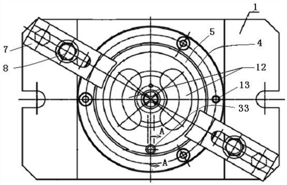
[0025] Example. Versatile milling fixture for machining such as Figure 7 to Figure 9 The oil separator of the piston pump of the quantitative motor series shown, the blank to be processed is in the shape of a disc, one side of the blank has a spherical surface 20 that bulges outward, the other side is a flat end surface 21, and the axis has a step center In the hole 22 , the outer side of the spherical surface 20 has a conical surface 27 connected to the peripheral surface, and the spherical surface 20 and the conical surface 27 are connected by a cylindrical surface 28 . It is necessary to machine the crescent hole 23, the groove 24 and the stepped hole 25 on the flat end surface 21, and machine eight small holes 26 on the spherical surface.

[0026] The structure of the multi-purpose milling fi...


PUM


Abstract

The invention discloses a multipurpose milling clamp which comprises a directional plug pin (6) and a base plate (1). A dabber (2) is arranged on the base plate (1). A positioning block (3) through which the dabber (2) penetrates is arranged at the top of the base plate (1). The outer ring of the top face of the positioning block (3) is an annular plane (4). A inwards-concave conical face (5) is connected to the inner side of the plane (4). The dabber (2) penetrates through the positioning block (3) along the axis of the conical face (5). A positioning hole (13) running through the base plate(1) is formed in the top face of the positioning block (3). A cylindrical pin (14) connecting the positioning block (3) with the base plate (1) is arranged inside the positioning hole (13). The two sides of the positioning block (3) are each provided with a compressing mechanism. The milling clamp is used for machining a fuel distributor and has the advantages of being low in total manufacturing cost, low in management cost and high in production efficiency, and the yield of finished products can be increased.

Description

technical field [0001] The invention belongs to the field of tooling for oil separators of plunger pumps of quantitative motor series, and in particular relates to a multi-purpose milling fixture. Background technique [0002] The blank of the oil separator of the piston pump of the quantitative motor series is in the shape of a disc. One side of the blank has a spherical surface bulging outward, the other side is a flat end surface, and the axis has a stepped center hole. The conical surface is connected by the surface, and the spherical surface and the conical surface are connected by the cylindrical surface. In the process from the blank to the finished oil separator, two processes are required. The first process is to locate the spherical surface and the center hole, press the flat end surface, and use the milling machine to process the crescent holes, grooves and stepped holes on the flat end surface; The last process is to locate the flat end face and the center hole,...

Claims


Application Information

Patent Timeline
Patent Type & Authority Applications(China)
IPC IPC(8): B23Q3/06
CPCB23Q3/062
Inventor 罗亚飞陈薪竹李道进
Owner AVIC LIYUAN HYDRAULIC
Why Eureka
Try Eureka