
Automatic power supply plug-in system of torpedo car and plug-in control method of torpedo car

A torpedo tank car and plugging system technology, which is applied in the direction of electrical program control, tank car, connecting device connection/disconnection, etc., can solve the problems of large deviation of locomotive parking position, low plugging success rate, and plugging effect is not as good as manual operation, etc. , to achieve the effect of improving the level of automated production, improving the level of safety production, and avoiding personal injury accidents

Active Publication Date: 2020-09-15
ANGANG STEEL CO LTD
View PDF10 Cites 4 Cited by
  • Summary
  • Abstract
  • Description
  • Claims
  • Application Information

AI Technical Summary

Problems solved by technology

[0003] There are two current power plugging methods: the first is manual plugging, where the power plug is manually picked up and inserted directly into the vehicle socket; manual plugging has strong adaptability and a high success rate of plugging, but it cannot meet the requirements of intelligent manufacturing. requirements, at the same time, it is also prone to personal injury accidents
The second is to use a robot to plug in. The robot picks up the power plug and plugs it into the vehicle socket; due to the large deviation of the parking position of the locomotive, it takes a long time for the robot to identify the socket and plug alignment, and the plugging effect is not as good as manual operation. The connection success rate is low, generally rarely more than 80%, and manual intervention is required, which greatly interferes with production

Method used


Image

  • Automatic power supply plug-in system of torpedo car and plug-in control method of torpedo car
  • Automatic power supply plug-in system of torpedo car and plug-in control method of torpedo car
  • Automatic power supply plug-in system of torpedo car and plug-in control method of torpedo car

Examples


Embodiment Construction

[0037] A further detailed description will be made below in conjunction with the specific structure and steps of a torpedo tank car power supply automatic plugging system and its control method according to the present invention.

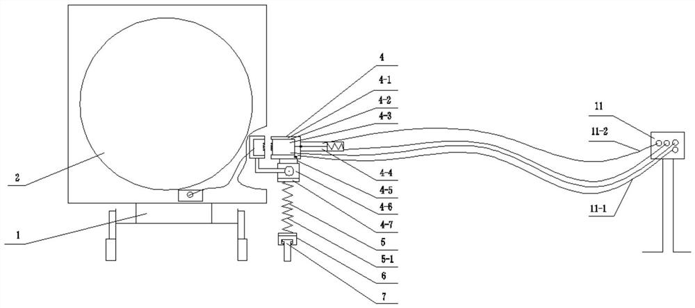
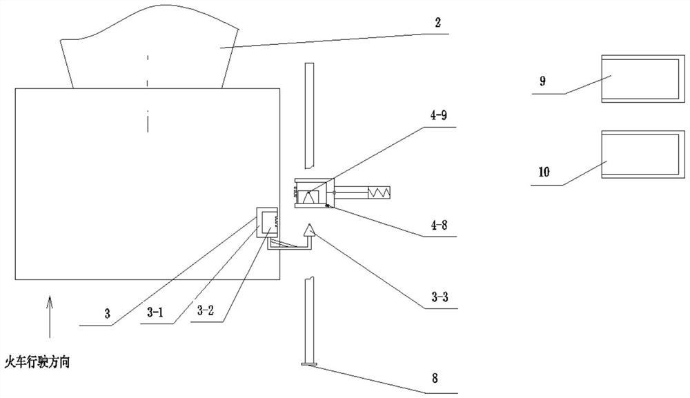
[0038] Such as figure 1 , figure 2 Shown is a schematic diagram of the composition and structure of the power supply automatic plugging system of the torpedo tanker of the present invention.

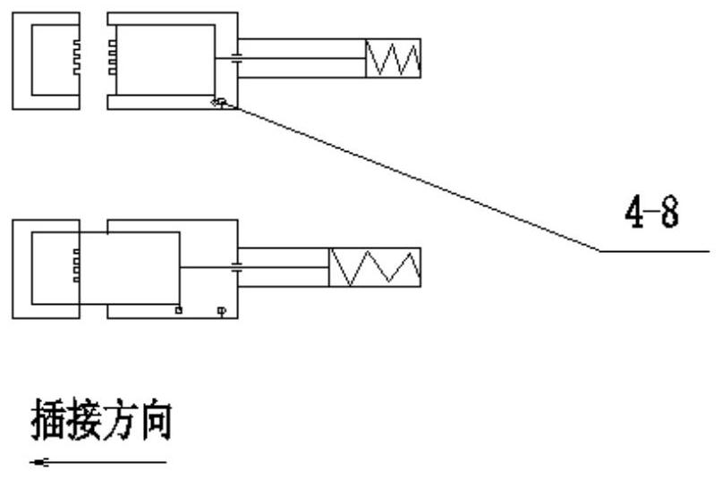
[0039] A power supply automatic plugging system for a torpedo tank car of the present invention comprises a socket device 3, a plug device 4 and its flexible support device 5, a follow-up trolley 6, a guide rail 7, a stop iron 8, a locomotive auxiliary operator 9, Auxiliary manipulator 10 for folding cans constitutes.

[0040] Described socket device 3 has a casing 3-1 that is installed on the torpedo tank car 1 car body, and a power socket 3-2 is housed in the casing 3-1. The power socket 3-2 is connected with the driving motor of the torpedo tank car 1. ...


PUM


Abstract

The invention discloses an automatic power supply plug-in system of a torpedo car and a plug-in control method of the torpedo car. A socket device is provided with a housing mounted on the torpedo car, a power supply socket is arranged in the housing, and a truncated cone is mounted on the housing; a plug device is also provided with a housing, a power supply plug capable of moving back and forthon a guide rail is arranged in the housing and is driven by an air cylinder, so that the plug device can be inserted into or separated from the socket; the plug device is provided with a hollow cone cavity, and the hollow cone cavity can be mutually embedded with the truncated cone; the plug device is installed on a follow-up trolley through a flexible supporting device, and the follow-up trolleyis installed on a rail section. The plug-in control method mainly comprises the following steps of: 1, applying for driving-in of the torpedo car; 2, performing automatic alignment; 3, performing plug-in operation, and connecting and detecting a power loop; 4, folding the torpedo car; and 5, allowing the torpedo car to leave and automatically disengage. The automatic production level of the torpedo tank car is improved, and personal injury accidents are avoided.

Description

technical field [0001] The invention relates to an automatic plugging device for a power supply, in particular to an automatic power supply plugging system for a torpedo tanker and a plugging control method thereof. Background technique [0002] The torpedo tank car used in the steel plant is a large-scale molten iron transportation equipment. The torpedo tank car itself has no power device, and it is usually pulled by a railway locomotive. After the molten iron is transported to the tank dumping station, the power supply is drawn from the electrical room of the tank dumping station, and the plug of the power supply is inserted into the on-board socket of the torpedo tanker, and the torpedo tanker is controlled to tip over through the electrical control system of the tank dumping station to complete the dumping of the molten iron. dump tasks. [0003] There are two current power plugging methods: the first is manual plugging, where the power plug is manually picked up and ...

Claims


Application Information

Patent Timeline
Patent Type & Authority Applications(China)
IPC IPC(8): B61D5/00B61C17/00B61D15/00H01R43/26G05B19/05
CPCB61C17/00B61D5/00B61D15/00G05B19/05H01R43/26
Inventor 吴丙恒
Owner ANGANG STEEL CO LTD
Learn More