Auxiliary power device and wheelbarrow including the same

A technology of power assist and power components, applied in the field of trolleys, can solve the problems of reduced practicability, high material cost, and difficulty in universal application, and achieve the effect of easy installation and low material cost

Inactive Publication Date: 2020-09-15
郑荣贵
View PDF0 Cites 0 Cited by
  • Summary
  • Abstract
  • Description
  • Claims
  • Application Information

AI Technical Summary

Problems solved by technology

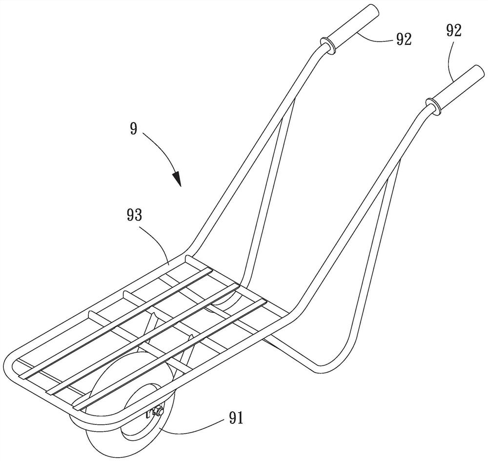
[0003] Above-mentioned existing trolley 9, owing to move with single wheel, can advance in narrow, rough terrain, but, use existing trolley 9 except providing the power of advancing, also must reach balance with extra applied force, when advancing in too much When the ground is inclined or the load is too heavy, more power needs to be applied to resist gravity, which makes it difficult for the existing trolley 9 to move forward when going uphill, and difficult to slow down when going downhill, thus reducing its practicability
In addition, it is also possible to change the cart to two wheels so that it is easier to achieve balance, but it cannot be used in a narrow environment, and it is difficult to use it in rough or muddy terrain due to the increased resistance from the ground, and it still cannot achieve the effect of labor saving.
[0004] By using a power device on the cart, such as a motor, electricity can provide additional power to assist the cart to move forward, so as to reduce manpower consumption. However, the price of existing electric pallet trucks is higher than that of ordinary carts, and it is difficult to be widely used.
Even if the above-mentioned existing trolley 9 is modified, it is still necessary to consider the weight distribution after modification and the power balance used, whether it can achieve the effect of labor saving, which leads to problems such as difficult installation of power auxiliary devices and high material costs

Method used


Image

  • Auxiliary power device and wheelbarrow including the same
  • Auxiliary power device and wheelbarrow including the same
  • Auxiliary power device and wheelbarrow including the same

Examples


Embodiment Construction

[0064] In order to make the above-mentioned and other objects, features and advantages of the present invention more obvious and understandable, the preferred embodiments of the present invention are listed below, together with the accompanying drawings, and are described in detail as follows:

[0065] The use of the quantifier "one" in the elements and components described throughout the present invention is only for convenience and to provide a common sense of the scope of the present invention; it should be interpreted as including one or at least one in the present invention, and a single concept also includes plural unless it is obvious that it is meant otherwise.

[0066]Approximate terms such as "combination", "combination" or "assembly" mentioned throughout the present invention mainly include forms that can be separated without destroying the components after connection, or that the components cannot be separated after connection, etc., which are common knowledge in th...


PUM


Abstract

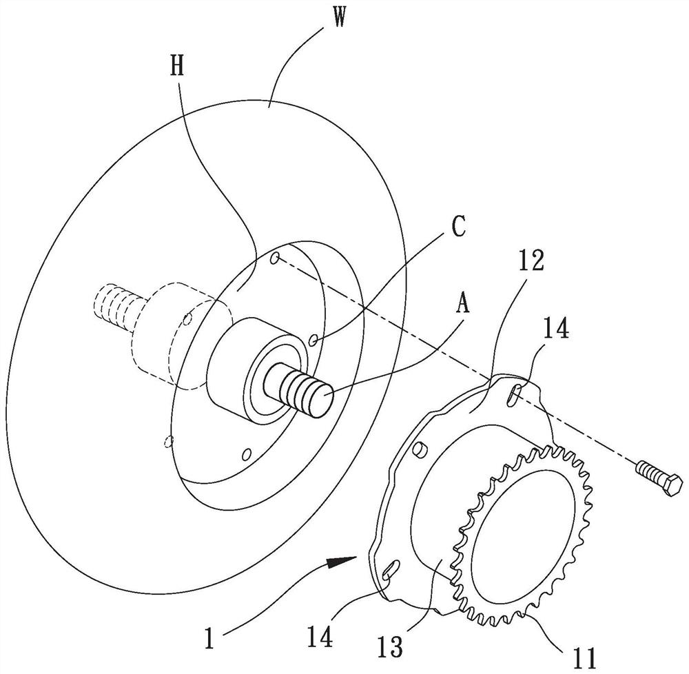
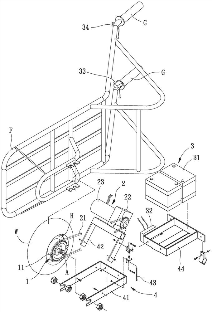
An auxiliary power device and a wheelbarrow including the same are provided. The auxiliary power device includes a driving member coupled with spokes of a wheel of a wheelbarrow via a positioning ring, a driving module including a connection member movably connected to an active portion and a driven portion of the driving member, and a support module including a first support pivotally connected to a second support and an adjustment screw located on two opposite edges of a triangle formed by the first and second supports. The first support is fixed to an axle and a frame of the wheelbarrow. The active portion is coupled with a power device fixed to an end of the second support distant to the first support. The power device is electrically connected to a power to form a power supply loop. The frame may be a barrow.

Description

technical field [0001] The invention relates to a trolley, in particular to a trolley with a power auxiliary device and the power auxiliary device. Background technique [0002] Please refer to figure 1 , which is a kind of existing trolley 9, the existing trolley 9 in the process of carrying goods, through a wheel 91 and two grips 92 to support the weight of the load, and through a bracket 93 to connect the wheel 91 and the Two grips 92, on which the bracket 93 can carry goods or install pallets, the operator applies an upward force to the two grips 92, the weight can be shared by the principle of leverage, and then through the two grips 92 and The bracket 93 pushes the wheel 91 to roll forward or backward with lateral force, so as to achieve the effect of moving goods. [0003] Above-mentioned existing trolley 9, owing to move with single wheel, can advance in narrow, rough terrain, but, use existing trolley 9 except providing the power of advancing, also must reach bala...

Claims


Application Information

Patent Timeline
IPC IPC(8): B62B1/10B62B5/00B62B5/04F16H7/02F16H7/06
CPCB62B1/10B62B5/0036B62B5/04F16H7/02F16H7/06
Inventor 郑荣贵
Owner 郑荣贵
Why Eureka
Try Eureka