Unpowered roller sorting slide way
A technology of rollers and slides is applied in the field of logistics sorting system equipment to achieve the effects of stable movement performance, good track retention performance, and good movement track retention.
- Summary
- Abstract
- Description
- Claims
- Application Information
AI Technical Summary
Problems solved by technology
Method used
Image

Examples
Embodiment 1
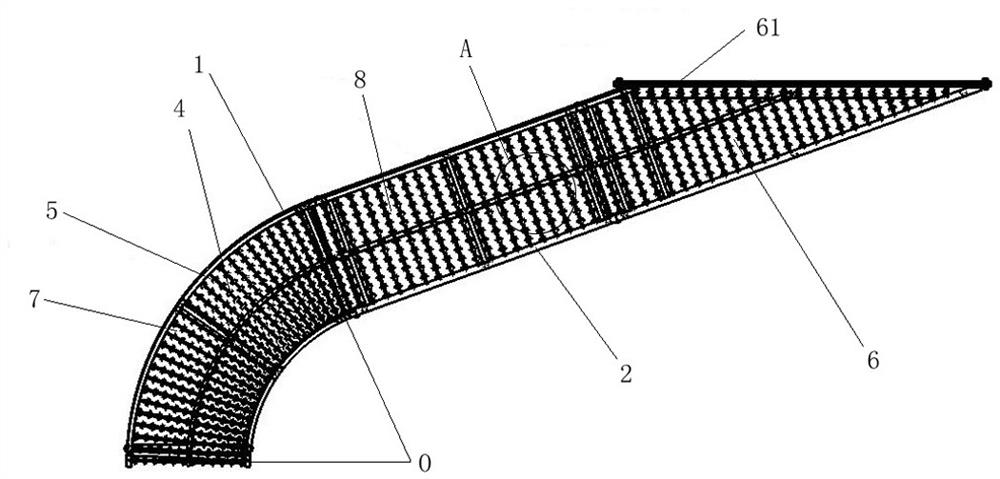
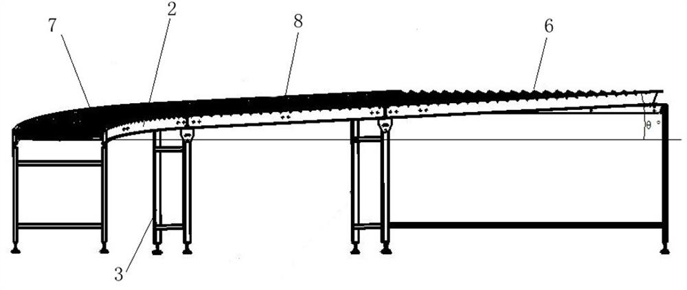
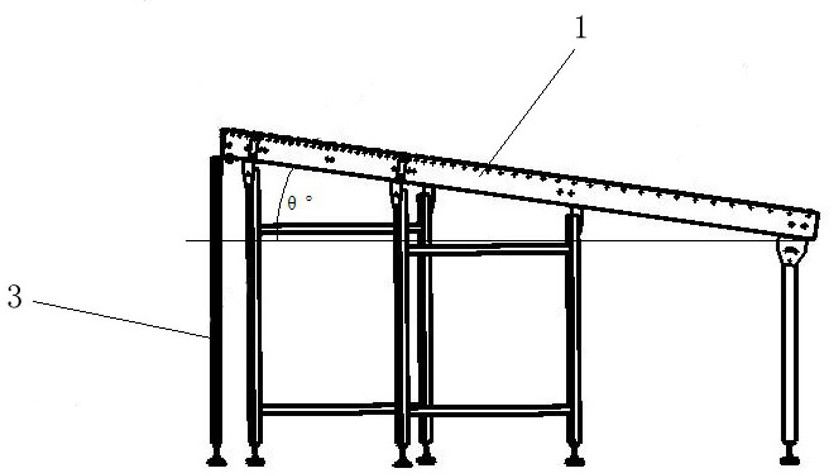
[0029] like figure 1 , 2 , 3, 4, 5, 6, and 7 show a kind of unpowered roller sorting chute, which includes a support foot 3 for supporting, and a first track extending in parallel and spaced in the horizontal projection direction above the support foot 3 1 and the second track 2, and the wheel axle 4 with a plurality of rollers 5 sleeved at intervals between the first track 1 and the second track 2.
[0030] Wherein the first track 1 and the second track 2 include a linearly extending introduction section 6 arranged from upstream to downstream and around a center of curvature ( figure 2 Center point O) is a circular arc-shaped steering section 7 with a curved circumference. Simultaneously in this embodiment, the first track 1 and the second track 2 also include a straight section 8, and the straight section 8 is a linear extension from the downstream end of the introduction section 6 to the upstream end of the diversion section 7, that is, it is connected between the introd...
Embodiment 2
[0042] The technical scheme described in embodiment two is similar to embodiment one, and its difference is:
[0043] In this embodiment, there is no direct connection between the introduction section 6 and the diversion section 7 without the straight section 8, so that the delivery of parcels can be realized in a smaller storage space with a shorter delivery length. This facilitates space layout.
[0044] In this embodiment, the included angle θ° is 10°, so as to achieve sufficient gravitational force in a small space to move the package downstream.
Embodiment 3
[0046] The technical solution recorded in the third embodiment is similar to that of the first embodiment, the difference is that:
[0047] In this embodiment, there is no direct connection between the introduction section 6 and the diversion section 7 without a straight section 8. At the same time, at the downstream end of the diversion section 7, a straight section 8 extending downward from its downstream end is provided to realize wrapping. Immediately turning after entering and backward linear transportation is convenient. On the one hand, setting the straight section can adapt to different storage space layouts; The function of containing the parcels can avoid problems such as a backlog caused by a large number of parcels coming to the end of the overall slide at the same time waiting for sorting.
[0048] In this embodiment, the included angle θ° is 6°, so as to provide a relatively small gravitational component force, thereby providing a relatively small acceleration on...
PUM
 Abstract
Description
Claims
Application Information