Hydraulic spike puller

a technology of spike puller and retraction tool, which is applied in the direction of manufacturing tools, crowbars, and ways, etc., can solve the problems of b>30/b> being vulnerable to damage, and achieve the effects of slowing down the movement of the piston, slowing down the retraction of the pulling tool, and speeding up the piston movemen

Active Publication Date: 2013-09-19
STANLEY WORKS THE
View PDF10 Cites 11 Cited by
  • Summary
  • Abstract
  • Description
  • Claims
  • Application Information

AI Technical Summary

Benefits of technology

[0021]Another aspect of the present invention is to provide a method of pulling a workpiece, such as for example, a spike, a fastener, etc., with a dual-stage retraction pulling tool, the pulling tool including a housing, a piston and a piston rod. The method includes flowing hydraulic fluid through a relatively smaller first area within the housing so as to provide a slower movement of the piston and a slower retraction of the pulling tool. The method also includes automatically changing an area through which the hydraulic fluid flows from the first area to a second area larger than the first area. The method further includes flowing the hydraulic fluid through the relatively larger second area within the housing so as to provide a faster movement of the piston and a faster retraction of the pulling tool.

Problems solved by technology

In addition, the use of external line 38 and check valve 39 may render the spike puller 30 vulnerable to damage.

Method used


Image

  • Hydraulic spike puller
  • Hydraulic spike puller
  • Hydraulic spike puller

Examples


Embodiment Construction

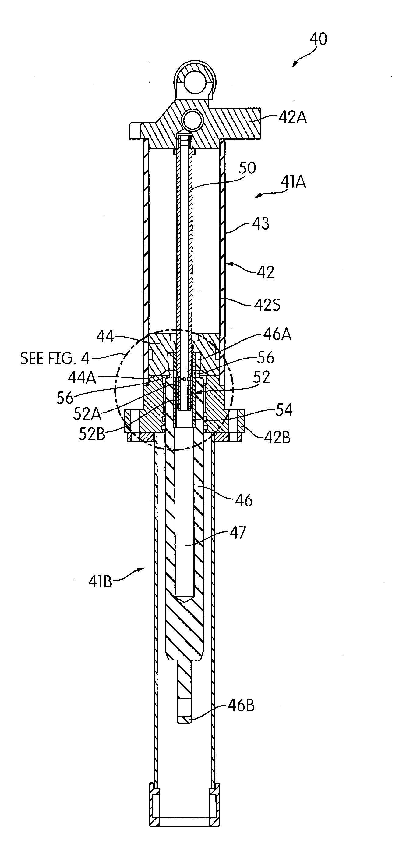
[0035]FIG. 3 is a cross-sectional view of a hydraulic spike puller 40, according to an embodiment of the present invention. Spike puller 40 has an upper body portion 41A and a lower body portion 41B. The upper body portion 41A includes a housing (e.g., cylinder) 42. The cylinder 42 includes a tubular portion 43 capped by head portion 42A and bottom portion 42B. Spike puller 40 also includes piston 44 configured to axially move within the cylinder 42. Fixed to piston 44 is piston rod 46. A first end 46A of piston rod 46 is connected to piston 44. A second end 46B of piston rod 46 is connected to a spike puller jaw assembly (not shown). Any type of spike puller jaw assembly can be connected piston rod 46. For example, a spike puller jaw assembly similar to jaw assembly 18 can be used. Piston rod 46 has a hollow axial bore 47 extending along most of a length of piston rod 46. Piston rod 46 is axially slideable within lower portion 41B.

[0036]Spike puller 40 further includes fixed hollow...


PUM

PropertyMeasurementUnit
diameter D6aaaaaaaaaa
sizeaaaaaaaaaa
internal dimensionaaaaaaaaaa

Abstract

A pulling tool includes a housing and a tube disposed within the housing, the tube configured to supply hydraulic fluid. The spike puller further includes a piston rod connected to a piston. The piston rod has a hollow axial bore, and the piston and the piston rod are axially moveable relative to the tube. The spike puller has a passage communicating fluid from the tube to the piston. The passage is contained within the housing. The passage is variable between a first configuration in which hydraulic fluid flows at a first restricted flow so as to provide a slower retraction of the piston rod and a second configuration in which hydraulic fluid flows at a second less restricted flow so as to provide a faster retraction of the piston rod.

Description

BACKGROUND OF THE INVENTION[0001]1. Field of the Invention[0002]The present invention pertains to hydraulic spike pullers or pulling tools.[0003]2. Discussion of Related Art[0004]Spike pullers are devices used to remove rail fasteners commonly called rail spikes. Currently, there exist numerous spike pullers in the market. In the present description, the term “spike puller” refers to a device that is capable of removing, extracting or pulling a rail spike.[0005]FIG. 1 shows a cross-sectional view of a conventional hydraulic spike puller 10 manufactured by Stanley Black and Decker, commonly referred to as Stanley Hydraulic Tool (SHT). SHT 10 has an upper body portion 11A and a lower body portion 11B. The upper portion 11A includes a housing (e.g., cylinder) 12. The cylinder 12 includes a tubular portion 13 capped by head portion 12A and bottom portion 12B. SHT 10 also includes piston 14 configured to axially move within the cylinder 12. Fixed to the underside of piston 14 is piston r...

Claims


Application Information

Patent Timeline
Patent Type & Authority Applications(United States)
IPC IPC(8): B25C11/00B23P11/00
CPCB25C11/00Y10T29/49822E01B29/26B25B7/00B25B9/00B25B33/00
Inventor CROVER, STEPHEN
Owner STANLEY WORKS THE
Why Eureka
Try Eureka