
Pile plate type ear wall type open cut tunnel structure

A technology of pile slab wall and ear wall, which is applied in the field of ear wall type open hole structure, can solve the problems of high foundation bearing capacity, large amount of concrete for structural size, uneven settlement, etc., to reduce volume and weight, and reduce building materials The effect of consumption and construction cost saving

Pending Publication Date: 2020-09-15
中铁二院贵阳勘察设计研究院有限责任公司
View PDF0 Cites 0 Cited by
  • Summary
  • Abstract
  • Description
  • Claims
  • Application Information

AI Technical Summary

Problems solved by technology

[0004] The existing ear wall-type open hole lining, the ear wall and the lining structure are poured separately, the ear wall is based on the gravity retaining wall design, the structural size and the amount of concrete are large, resulting in poor integrity of the open hole structure and a large difference in stiffness. High requirements for foundation bearing capacity, prone to uneven settlement, high civil construction costs and high operational risks

Method used


Image

  • Pile plate type ear wall type open cut tunnel structure
  • Pile plate type ear wall type open cut tunnel structure
  • Pile plate type ear wall type open cut tunnel structure

Examples


Embodiment Construction

[0019] The present invention will be further described below in conjunction with the accompanying drawings and embodiments.

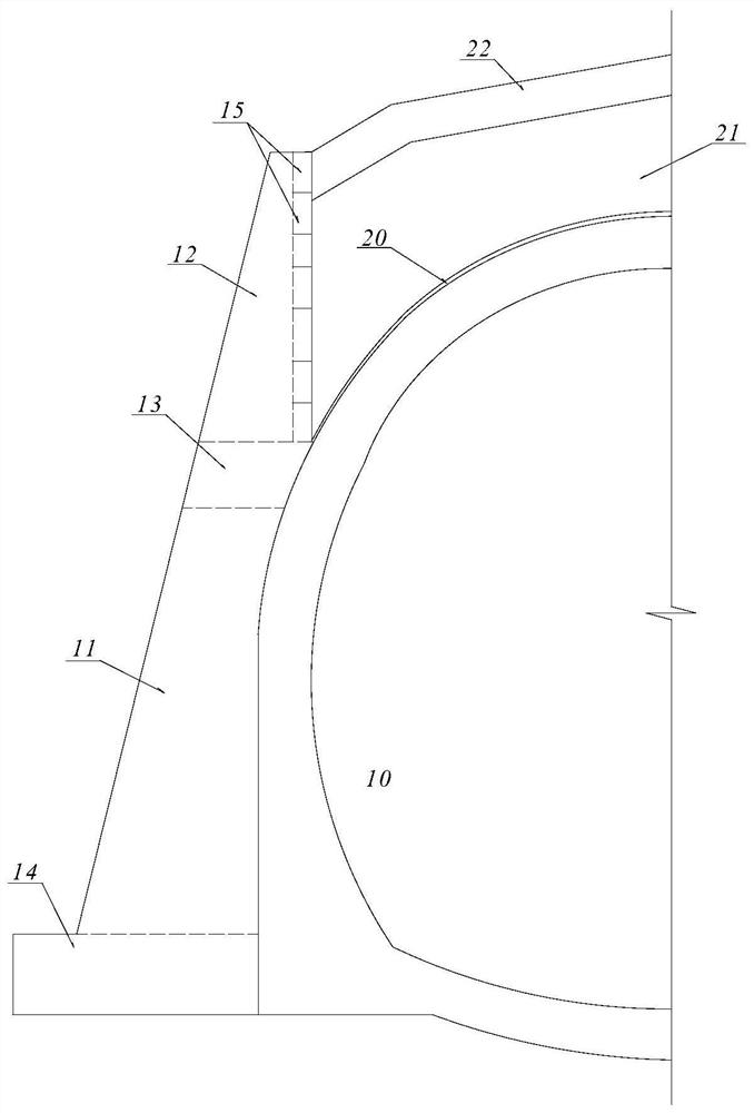
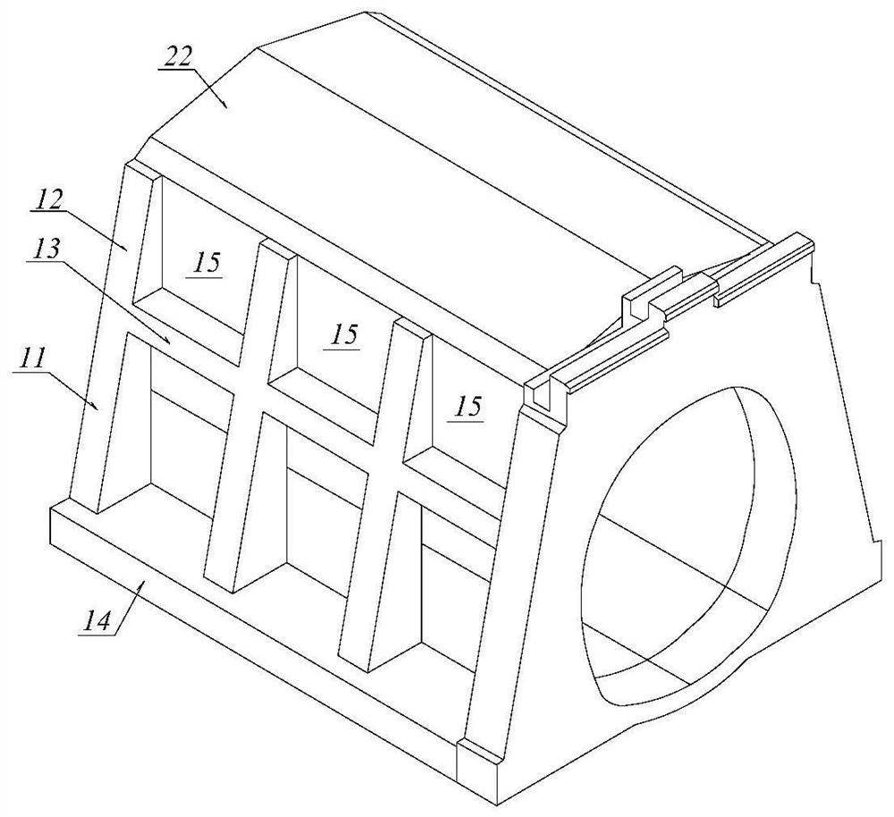
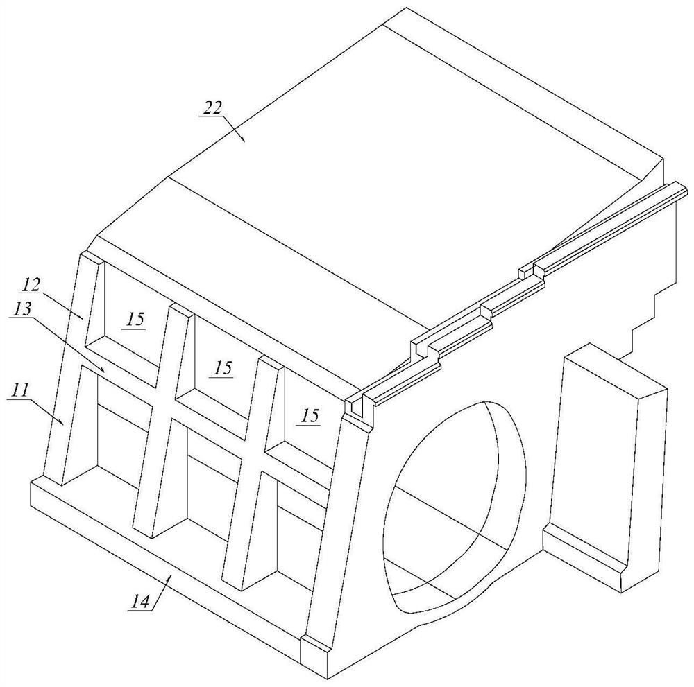
[0020] refer to figure 1 , a pile plate type ear wall type open hole structure of the present invention includes a lining structure 10 and ear wall structures arranged on one side or both sides of the lining structure 10 in the lateral direction, and the ear wall structure includes ear walls arranged at intervals along the extending direction of the open hole. The wall column is characterized in that: the ear wall column is divided into two sections, the lower ear wall column 11 and the upper ear wall column 12, and a bottom plate 14 is arranged at the lower end of the lower ear wall column 11 to connect each ear wall column horizontally, The lower end of the upper ear wall column 12 is provided with a beam 13 that connects each ear wall column horizontally as a whole, and the bottom plate 14, the beam 13 and each ear wall column form a reinforced concr...


PUM


Abstract

The invention discloses a pile plate type ear wall type open cut tunnel structure. The pile plate type ear wall type open cut tunnel structure aims to effectively improve the integrity of an open cuttunnel structure, reduce the risk of differential settlement and reduce the size and the dead weight of an ear wall structure, so that the construction cost is saved. The pile plate type ear wall typeopen cut tunnel structure is characterized in that each ear wall column is divided into a lower ear wall column section and an upper ear wall column section, bottom plates for transversely connectingeach ear wall column into a whole are arranged at the lower ends of the lower ear wall column sections, cross beams for transversely connecting each ear wall column into a whole are arranged at the lower ends of the upper ear wall column sections, and the bottom plates, the cross beams and each ear wall column form a reinforced concrete frame structure; precast concrete slabs are arranged at thesoil retaining side of each upper ear wall column in the upper space of the ear wall structure above the cross beams to form a pile plate wall structure used for bearing lateral backfill soil pressure; and in the lower space of the ear wall structure from the cross beams to the bottom plates, the lower ear wall columns and the side wall section of a lining structure are fixedly connected into a whole to form a pile plate wall structure used for bearing acting force such as lateral soil pressure, structural dead weight, and seismic force of the open cut tunnel structure.

Description

technical field [0001] The invention relates to the main structure of tunnel engineering, in particular to a pile plate type ear wall type open hole structure. Background technique [0002] In the engineering design of tunnels in mountainous areas, according to factors such as the topography and geology of the entrance, ear-wall open hole structures are often used, including single-pressure open holes and double-ear open holes. [0003] The main body of the ear wall type open hole structure is composed of two parts: the ear wall and the lining structure. There are ear walls on one or both sides of the lining structure. The top of the open hole is backfilled with earth and rocks and a water-resistant layer is set up to buffer against collapsed blocks and falling rocks. Features. [0004] The existing ear wall-type open hole lining, the ear wall and the lining structure are poured separately, the ear wall is based on the gravity retaining wall design, the structural size and ...

Claims


Application Information

Patent Timeline
IPC IPC(8): E02D17/20E21D11/10A01G9/02E02D29/02
CPCE02D17/20E21D11/10A01G9/02E02D29/02E02D29/0266
Inventor 康力方钱宝陶伟明杨翔
Owner 中铁二院贵阳勘察设计研究院有限责任公司
Learn More