Sample application instrument

A technology of a spotting device and a sample plate, applied in the field of spotting devices, can solve the problems of difficult to meet large-scale and mechanized production, large loss of the tip of the spotting needle, and difficulty of the piezoelectric ceramic nozzle, and achieves fast spotting speed and structure. Simple, high-efficiency spotting effect

Pending Publication Date: 2020-09-15
SHANGHAI BAIO TECH
View PDF9 Cites 2 Cited by
  • Summary
  • Abstract
  • Description
  • Claims
  • Application Information

AI Technical Summary

Problems solved by technology

This method has a fast spotting speed, but the volume of the sprayed sample is very small. It is very difficult for the piezoelectric ceramic nozzle to deal with liquids with high viscosity, and it has high requirements for the spotting environment such as temperature and humidity. , it is difficult to meet the large-scale and mechanized production, and the cost is high
[0005] The contact pin spotting instrument makes the spotting pin directly contact with the surface of the solid support, and leaves the sample on the solid support. The spotting pin is usually a solid pin or a pen-tip slit pin, etc., and its influence on the spotting environment The requirements are low, but the sampling speed is slow, and the tip of the sampling needle is worn out by contact sampling, and the life of the sampling needle is short

Method used


Image

  • Sample application instrument
  • Sample application instrument
  • Sample application instrument

Examples


Embodiment Construction

[0034] The present invention will be further described in detail below in conjunction with the accompanying drawings of the specification. The structure of the spotter and the like are schematically and simplified in the drawings.

[0035] In the description of the present invention, it should be understood that the terms "upper", "lower", "front", "rear", "left", "right", "top", "bottom", "inner", " The orientation or positional relationship indicated by “outside” is based on the orientation or positional relationship shown in the drawings, and is only for the convenience of describing the present invention and simplifying the description, and does not indicate or imply that the device or element referred to must have a specific orientation to The specific azimuth structure and operation cannot be understood as a limitation of the present invention.

[0036] (The overall structure of the spotter)

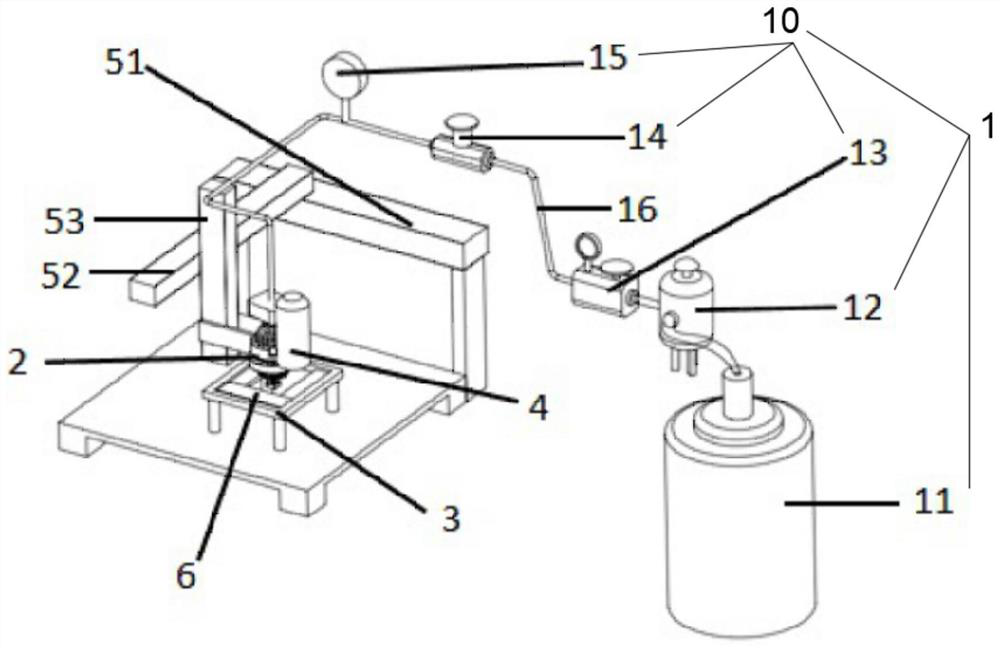
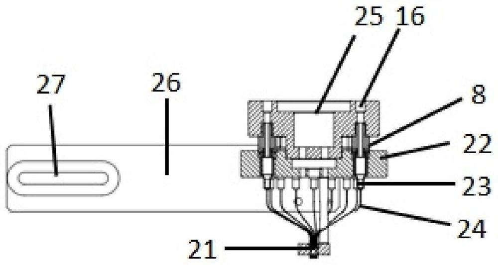
[0037] See figure 1 with figure 2 As shown, the spotting instrument of this embodi...


PUM


Abstract

The invention relates to the technical field of medical instruments, and discloses a sample application instrument, which comprises a gas path module and a liquid path module comprising a liquid storage bin and a liquid conveying pipe. The gas path module is communicated with the liquid storage bin, and one end of the liquid conveying pipe is communicated with the liquid storage bin; the gas pathmodule adjusts the air pressure in the liquid storage bin so as to control liquid discharging of the other end of the liquid conveying pipe. According to the sample application instrument disclosed bythe invention, the liquid outlet of the liquid conveying pipe in the liquid path module is controlled by arranging the gas path module, the sample liquid is promoted to flow out of the liquid conveying pipe by utilizing micro-pressure, the sample liquid is controlled by the air pressure, and is contacted with a sample application plate at the dripping moment to form an array, so that sample application is completed. The sample application instrument simultaneously solves the technical problems of a non-contact injection sample application instrument and a contact needle sample application instrument, a semi-contact sample application method is innovated, and the sample application method has the advantages of large sample point volume, low requirement on sample application environment andhigh sample application speed, a problem of abrasion of a needle head of a sample application needle is solved, and the sample application instrument is suitable for large-scale industrial production.

Description

Technical field [0001] The present invention relates to the technical field of medical devices, in particular to a spotting instrument. Background technique [0002] A spotting instrument, such as a biochip spotting instrument, is used to quickly and accurately place reagents, such as oligonucleotides, antibodies, proteins and other biological reagents, on the spotting plate (aldehyde-modified glass slides, silicon Film, etc.) on. [0003] Classified according to the spotting method, the existing spotting instruments are divided into non-contact jet spotting instruments and contact needle spotting instruments. [0004] The non-contact jet spotting instrument usually uses a piezoelectric nozzle to control the amount of spray dots. The cavity and small nozzles are etched on the silicon wafer. The back of the cavity is pasted with piezoelectric ceramics, and voltage is applied to the piezoelectric ceramics during operation. , The piezoelectric ceramic produces deformation and drives t...

Claims


Application Information

Patent Timeline
Patent Type & Authority Applications(China)
IPC IPC(8): G01N1/28
CPCG01N1/28
Inventor 朱滨邢军芬徐建刚
Owner SHANGHAI BAIO TECH
Why Eureka
Try Eureka