Low-power-consumption intelligent lighting fingerprint lock and lighting method thereof
A technology of intelligent lighting and lighting method, applied in the field of smart locks, can solve the problems that users cannot accurately know the specific location of the fingerprint area, affect the user experience, and affect the normal door opening operation, etc., and achieve the effect of low power consumption
- Summary
- Abstract
- Description
- Claims
- Application Information
AI Technical Summary
Problems solved by technology
Method used
Image
Examples
Embodiment 1
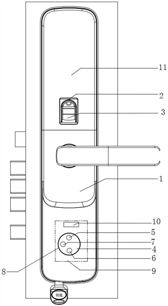
[0036] A low-power smart lighting fingerprint lock, such as figure 1 As shown, the lock body of the fingerprint lock is provided with a front panel 1, the front panel 1 is provided with a fingerprint area, and the fingerprint area is provided with a fingerprint device 3, which can be used for fingerprint identification through the fingerprint device 3. The fingerprint device 3 is provided with an illumination lamp 2 for illumination.
[0037] In this embodiment, the front panel 1 is further provided with a password verification area 11, and the password verification area 11 is provided with a backlight plate, and the backlight plate is provided with a plurality of backlight lamps, each of which is provided with a backlight. The light corresponds to a password key, and all the backlight lights on the password verification area 11 can be lit at the same time or individually. The backlight panel is connected to the control output end of the controller 10, and the controller 10 c...
Embodiment 2
[0047] A lighting method for a low-power smart lighting fingerprint lock, which is applied to the low-power smart lighting fingerprint lock in the first embodiment, such as Figure 5 shown, including:
[0048] Step S1: The timing module will send a brightness trigger signal to the controller 10 according to the preset time timing, and after the controller 10 receives the brightness trigger signal, it outputs a low output pin to the output pin connected to the power switch circuit 12. At this time, the power switch circuit 12 is turned on and provides the brightness detection module 7 with a voltage of 3.3V, so that the brightness detection module 7 starts to work. The brightness detection module 7 starts and detects the ambient brightness parameters in the current environment, and feeds them back to the controller 10;
[0049] Step S2: the controller 10 judges whether the ambient brightness parameter is less than the threshold value, if it is less than the threshold value, it...
PUM
 Abstract
Description
Claims
Application Information
 - R&D
- Intellectual Property
- Life Sciences
- Materials
- Tech Scout
- Unparalleled Data Quality
- Higher Quality Content
- 60% Fewer Hallucinations
Browse by: Latest US Patents, China's latest patents, Technical Efficacy Thesaurus, Application Domain, Technology Topic, Popular Technical Reports.
© 2025 PatSnap. All rights reserved.Legal|Privacy policy|Modern Slavery Act Transparency Statement|Sitemap|About US| Contact US: help@patsnap.com


