Three-phase CLLC bidirectional direct-current converter and control method thereof

A bidirectional DC conversion and three-phase technology, applied in the direction of DC power input conversion to DC power output, irreversible DC power input conversion to AC power output, control/regulation systems, etc., can solve poor reliability and clamp tube voltage High stress, large quantity, etc.

Inactive Publication Date: 2020-09-15
INST OF ELECTRICAL ENG CHINESE ACAD OF SCI
View PDF3 Cites 7 Cited by
  • Summary
  • Abstract
  • Description
  • Claims
  • Application Information

AI Technical Summary

Problems solved by technology

[0005] In order to solve the above-mentioned problems in the prior art, that is, the existing high-voltage side series-low-voltage side parallel structure based on modularization has a large number of modules and poor reliability, and the existing multi-level technology-based converter circuit topology increases with the high-voltage side voltage To solve the problems of complex, uneven capacitor voltage division, and high voltage stress of the clamp tube, the present invention provides a three-phase CLLC bidirectional DC converter, which includes sequentially connected high-voltage side voltage-dividing capacitor modules, three-phase Bridge series module, three-phase primary side resonant module, three-phase isolation transformer, three-phase secondary side resonant module, three-phase half-bridge parallel module, low-voltage side capacitor module;

Method used


Image

  • Three-phase CLLC bidirectional direct-current converter and control method thereof
  • Three-phase CLLC bidirectional direct-current converter and control method thereof
  • Three-phase CLLC bidirectional direct-current converter and control method thereof

Examples


Embodiment Construction

[0054] The application will be further described in detail below in conjunction with the accompanying drawings and embodiments. It should be understood that the specific embodiments described here are only used to explain related inventions, not to limit the invention. It should also be noted that, for the convenience of description, only the parts related to the related invention are shown in the drawings.

[0055] It should be noted that, in the case of no conflict, the embodiments in the present application and the features in the embodiments can be combined with each other. The present application will be described in detail below with reference to the accompanying drawings and embodiments.

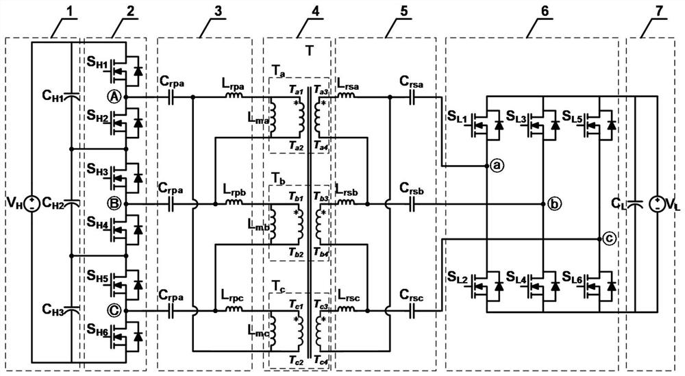
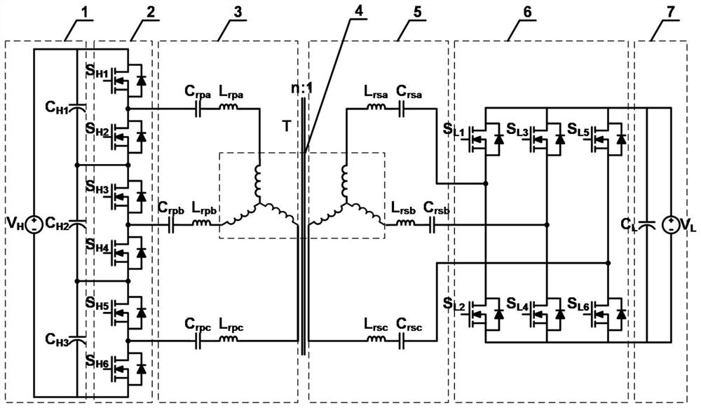
[0056] A three-phase CLLC bidirectional DC converter of the present invention, the DC converter includes a high-voltage side voltage-dividing capacitor module, a three-phase half-bridge series module, a three-phase primary-side resonance module, a three-phase isolation transformer, a...


PUM


Abstract

The invention belongs to the technical field of direct-current converters, particularly relates to a three-phase CLLC bidirectional direct-current converter and a control method thereof, and aims at solving the problems that the existing high voltage side series-low voltage side parallel structure based on modularization is large in number of modules, the reliability is poor, and the existing converter based on a multi-level technology is complex in circuit topology, uneven in capacitance voltage division and high in clamping tube voltage stress. The three-phase CLLC bidirectional direct-current converter comprises a high-voltage side voltage-dividing capacitor module, a three-phase half-bridge series / parallel module, a three-phase primary side / secondary side resonance module, a three-phase isolation transformer and a low-voltage side capacitor module, wherein the high-voltage side voltage-dividing capacitor module comprises three voltage-dividing capacitors; the three-phase half-bridge series / parallel module comprises three bridge arms which are connected in series / parallel, and each bridge arm comprises two switching tubes which are connected in series; the three-phase primary side / secondary side resonance module comprises an a-phase primary side / secondary side resonance cavity, a b-phase primary side / secondary side resonance cavity and a c-phase primary side / secondary side resonance cavity; and the three-phase isolation transformer comprises a single-phase transformer a, a single-phase transformer b and a single-phase transformer c. High-voltage side voltage division iscarried out through the voltage-dividing capacitor, the voltage stress of a clamping tube is reduced, the switching loss is reduced through the high-frequency soft switching technology, and the efficiency and the power density of the converter are improved.

Description

technical field [0001] The invention belongs to the technical field of DC converters, and in particular relates to a three-phase CLLC bidirectional DC converter and a control method thereof. Background technique [0002] The bidirectional DC converter can change the direction of the input and output current while keeping the input and output voltage constant, and realize the bidirectional transmission of energy. It is a key device for DC voltage conversion and power control. With the rapid development of renewable energy distributed generation systems and DC distribution network technology, bidirectional DC converters suitable for high-voltage and high-power applications have become one of the important development directions and research hotspots in recent years. [0003] In the DC distribution network and renewable energy DC power generation system, the high-voltage side voltage can be as high as several kV to tens of kV. Due to the low breakdown voltage of conventional po...

Claims


Application Information

Patent Timeline
Patent Type & Authority Applications(China)
IPC IPC(8): H02M3/335H02M7/48
CPCH02M3/3353H02M3/33592H02M7/48H02M7/4818Y02B70/10
Inventor 曹国恩王一波曹睿王哲赵勇
Owner INST OF ELECTRICAL ENG CHINESE ACAD OF SCI
Why Eureka
Try Eureka