
Charge circuit structure with three-phase electric power

A charging circuit and three-phase power technology, which is applied to battery circuit devices, circuit devices, collectors, etc., can solve the problems of difficulty in improving charging speed, high voltage stress of switch tubes, and low energy utilization rate, so as to reduce capacitor voltage , Reduce voltage stress, high power utilization

Pending Publication Date: 2018-06-29
CHINA UNIV OF MINING & TECH (BEIJING) +1
View PDF0 Cites 1 Cited by
  • Summary
  • Abstract
  • Description
  • Claims
  • Application Information

AI Technical Summary

Problems solved by technology

For example: (1) The charging power supply for battery electric locomotives in coal mines has the characteristics of high input voltage (660V / 1140V), high output power, and requires flameproofing. Although high-frequency switching power supply or phase-controlled silicon-controlled silicon technology is used, There are still problems such as high voltage stress of the switching tube, low power factor, low efficiency, and large harmonic current; (2) the charging power supply of electric vehicles. Electric vehicles are used as green and energy-saving vehicles, but the existing charging piles still have low power factors. , low efficiency and other issues, not only make it difficult to increase the charging speed, but also waste electric energy resources; (3) The energy storage equipment used for wind energy and solar lamp renewable resource power generation, due to the randomness and volatility of renewable energy power generation The characteristics of the charging circuit require particularly high energy utilization, adaptability, and reliability, but the existing technology has problems such as low energy utilization, poor adaptability, high hardware cost, and poor reliability.

Method used


Image

  • Charge circuit structure with three-phase electric power
  • Charge circuit structure with three-phase electric power
  • Charge circuit structure with three-phase electric power

Examples


Embodiment Construction

[0023] The structure of the three-phase electric charging circuit of the present invention will be explained and described in detail below in conjunction with the accompanying drawings.

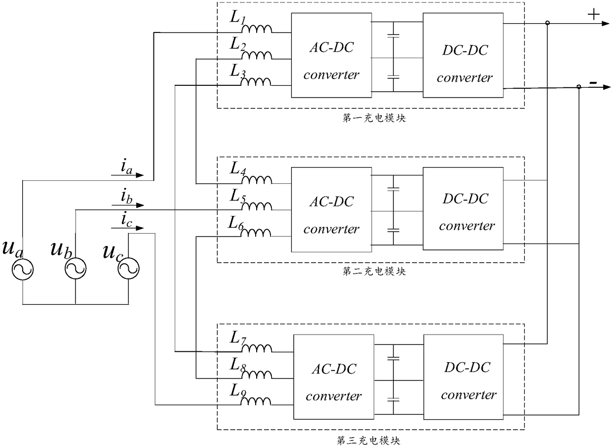
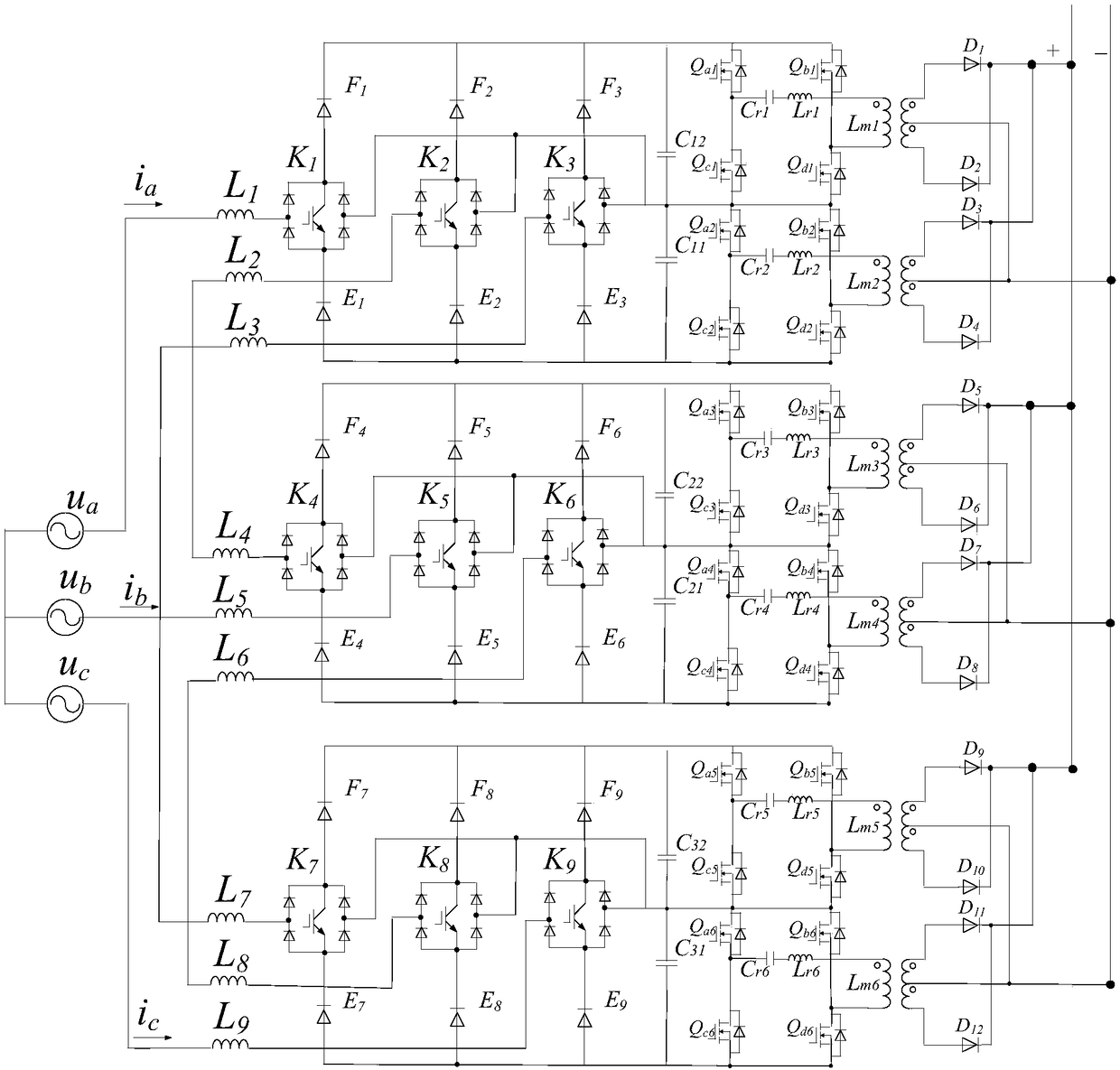
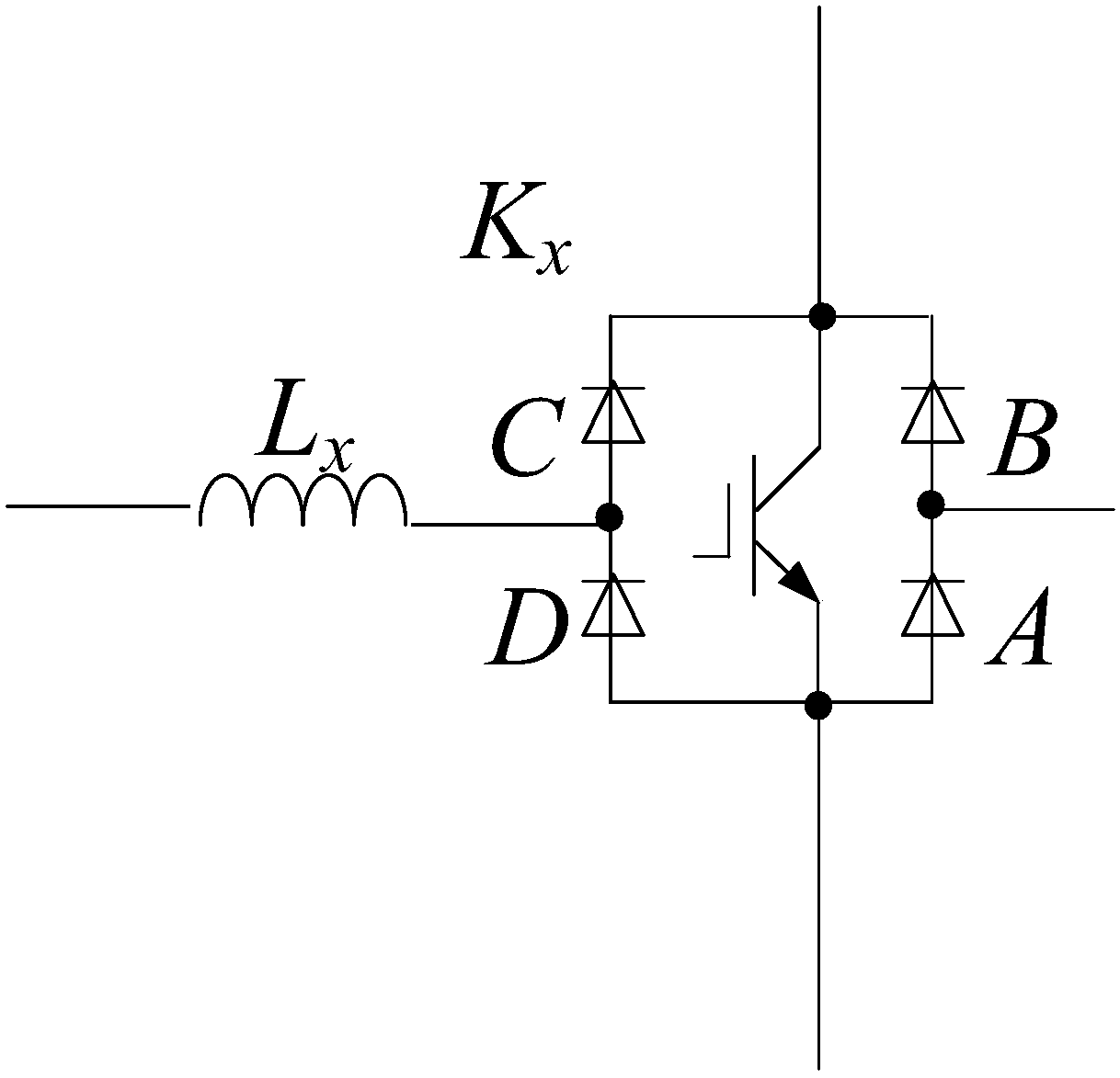
[0024] Such as Figures 1 to 3 As shown, this embodiment discloses a three-phase electric charging circuit structure, the circuit structure includes a first charging module POWER1, a second charging module POWER2 and a third charging module POWER3, in this embodiment, these three charging modules The structure is exactly the same; the details are as follows.

[0025] Such as figure 2 As shown, the first charging module has a first input terminal, a second input terminal and a third input terminal, the second charging module has a fourth input terminal, a fifth input terminal and a sixth input terminal, and the third charging module has a seventh input terminal. The input terminal, the eighth input terminal and the ninth input terminal, wherein, each input terminal is not shown in the figur...


PUM


Abstract

The invention discloses a charge circuit structure with three-phase electric power. The charge circuit structure comprises a first charge module, a second charge module and a third charge module. Thefirst charge module is provided with a first input end, a second input end and a third input end, the second charge module is provided with a fourth input end, a fifth input end and a sixth input end,and the third charge module is provided with a seventh input end, an eighth input end and a ninth input end; the first input end, the fifth input end and the ninth input end are connected with threeoutput ends of a three-phase input power source; the second input end and the fourth input end are connected with each other, the third input end and the seventh input end are connected with each other, the sixth input end and the eighth input end are connected with each other, and output ends of the first charge module, the second charge module and the third charge module are connected with one another in parallel; the various charge modules comprise rectifiers and direct-current converters which are sequentially connected with one another. The novel charge circuit structure has the advantages that the quantities of electronic switch devices can be effectively reduced, the withstand voltage grades of switch devices can be lowered to a great extent, accordingly, the circuit construction cost can be reduced, and the charge circuit structure can be effectively applied to high-voltage and high-power places.

Description

technical field [0001] The present invention relates to the technical field of charging power supply, and more specifically, the present invention relates to a three-phase electric charging circuit structure. Background technique [0002] At present, charging power sources that use three-phase power as input have been widely used. For example: (1) The charging power supply for battery electric locomotives in coal mines has the characteristics of high input voltage (660V / 1140V), high output power, and requires flameproofing. Although high-frequency switching power supply or phase-controlled silicon-controlled silicon technology is used, There are still problems such as high voltage stress of the switching tube, low power factor, low efficiency, and large harmonic current; (2) the charging power supply of electric vehicles. Electric vehicles are used as green and energy-saving vehicles, but the existing charging piles still have low power factors. , low efficiency and other i...

Claims


Application Information

Patent Timeline
IPC IPC(8): H02J7/02H02M7/217H02M7/219
CPCH02J7/022H02M7/2173H02M7/219H02J2207/20H02M1/0067H02M1/007
Inventor 邹甲王聪卢其威程红苏勇
Owner CHINA UNIV OF MINING & TECH (BEIJING)
Learn More