
Double-layer air duct heat dissipation device

A heat dissipation device and air duct technology, which is applied in the direction of deicing/drying device, cooling/ventilation/heating transformation, electrical equipment structural parts, etc., can solve the problem of poor temperature uniformity of T/R components, long air flow path, and resistance to harsh conditions The ability of the environment is poor and other problems, to achieve the effect of achieving temperature uniformity and shortening the flow path

Active Publication Date: 2020-09-15
西安黄河机电有限公司
View PDF6 Cites 0 Cited by
  • Summary
  • Abstract
  • Description
  • Claims
  • Application Information

AI Technical Summary

Problems solved by technology

Liquid cooling requires a complete liquid cooling system. For lightweight and high-mobility radars, due to stricter requirements on weight and volume, liquid cooling is not suitable; most air cooling systems use open air cooling Therefore, the ability to resist harsh environments is poor, and the active phased array antenna cannot be protected from dust, water, and salt spray; there are also closed air-cooled structures that use cooling air ducts, and the way is to blow air at one end of the air duct or One end draws air or both are used at the same time; these air cooling methods solve the heat dissipation problem of T / R components to a certain extent, but there are also disadvantages such as long air flow paths, large wind resistance, and poor temperature uniformity of T / R components. When the number of R component arrays is large, this kind of cooling device will not be able to meet the temperature uniformity requirements of T / R components

Method used


Image

  • Double-layer air duct heat dissipation device
  • Double-layer air duct heat dissipation device
  • Double-layer air duct heat dissipation device

Examples


Embodiment Construction

[0036] Example embodiments will now be described more fully with reference to the accompanying drawings. Example embodiments may, however, be embodied in many forms and should not be construed as limited to the examples set forth herein; rather, these embodiments are provided so that this disclosure will be thorough and complete and fully convey the concept of example embodiments to those skilled in the art. The described features, structures, or characteristics may be combined in any suitable manner in one or more embodiments.

[0037] In addition, the drawings are merely schematic illustrations of embodiments of the present invention and are not necessarily drawn to scale. The same reference numerals in the drawings denote the same or similar parts, and thus repeated descriptions thereof will be omitted. Some of the block diagrams shown in the drawings are functional entities and do not necessarily correspond to physically or logically separate entities.

[0038] In this ...


PUM


Abstract

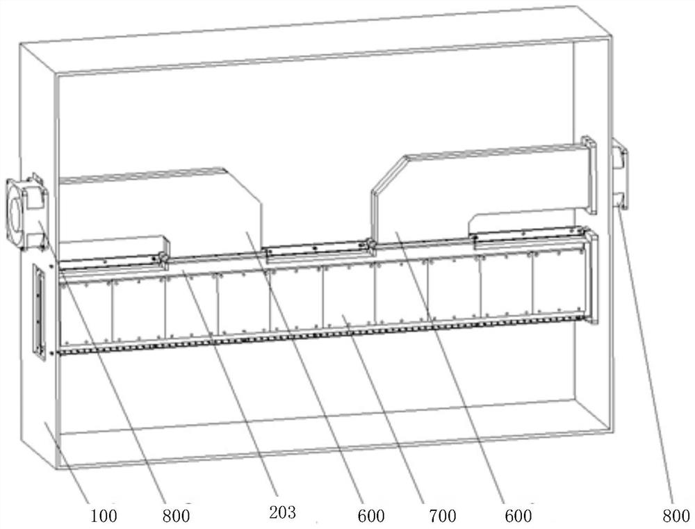
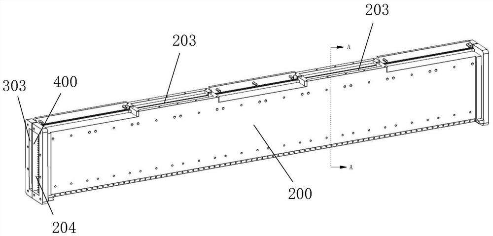
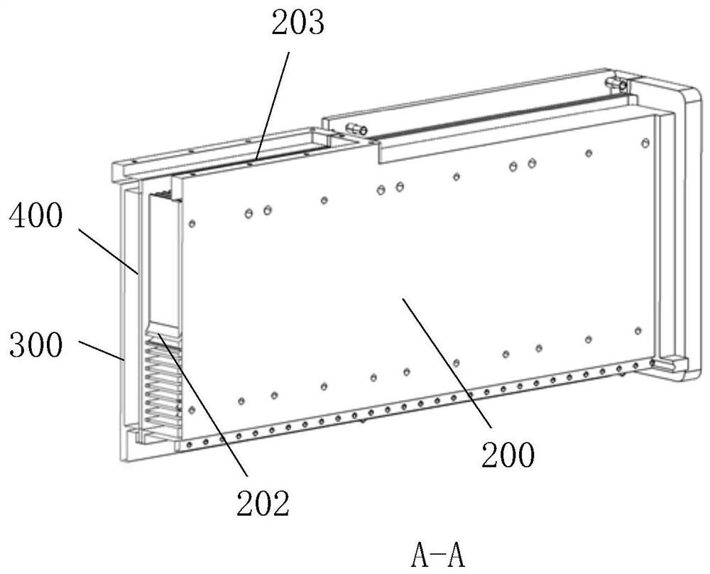
The embodiment of the invention relates to a double-layer air duct heat dissipation device. The device comprises a long-strip radiator, an air duct shell and a partition plate, wherein two end parts of the long-strip-shaped radiator are arranged on a shell, and a first baffle plate is arranged in the middle of the long-strip-shaped radiator; the air duct shell is used for being installed in cooperation with the long-strip-shaped radiator, a second baffle is arranged in the middle of the air duct shell, and the second baffle corresponds to the first baffle in position; the partition plate is arranged between the long-strip-shaped radiator and the air duct shell and used for connecting the long-strip-shaped radiator with the air duct shell, and the partition plate is provided with a plurality of through holes used for communicating the long-strip-shaped radiator with the air duct shell so as to form a double-layer heat dissipation air duct between the long-strip-shaped radiator and the air duct shell. According to the embodiment of the invention, the flow path of air in the air duct in the gaps of cooling fins is shortened, and the temperature uniformity requirement during array arrangement of a plurality of T / R assemblies is met.

Description

technical field [0001] Embodiments of the present invention relate to the technical field of heat dissipation of electronic equipment, and in particular to a double-layer air duct heat dissipation device. Background technique [0002] A large number of highly dense T / R components are installed in the active phased array antenna, and the microwave power devices in the T / R components are mostly miniaturized microwave integrated circuits. Due to low efficiency, T / R components will generate a lot of heat loss, which will cause the temperature of T / R components to rise sharply. Excessive temperature will affect the working performance and service life of components, and may cause damage to components in severe cases. , therefore, heat dissipation design is a very important issue in active phased array antennas. [0003] The heat dissipation methods currently applied to active phased array antennas mainly include liquid cooling and air cooling. Liquid cooling requires a complete...

Claims


Application Information

Patent Timeline
Patent Type & Authority Applications(China)
IPC IPC(8): H05K7/20H01Q1/00
CPCH05K7/20136H05K7/20145H01Q1/02
Inventor 刘卫刚薛敏赵冬竹董波王兴伟
Owner 西安黄河机电有限公司
Learn More