
Pump body molding and cooling device for production of electromechanical equipment

A technology of electromechanical equipment and cooling devices, applied in quenching devices, heat treatment equipment, metal processing equipment, etc., can solve the problems of low cooling liquid temperature drop, high cooling liquid temperature, and low heat dissipation efficiency, so as to ensure the dissipation performance , increase the surface area, improve the cooling effect of cold air

Inactive Publication Date: 2020-09-18
烟台福慧智能科技有限公司
View PDF0 Cites 1 Cited by
  • Summary
  • Abstract
  • Description
  • Claims
  • Application Information

AI Technical Summary

Problems solved by technology

However, the design of the above-mentioned patent to solve the problem that the temperature of the cooling liquid will gradually rise is relatively simple, the heat dissipation efficiency is not high, and the overall cooling temperature of the cooling liquid is low, so there are certain limitations.

Method used


Image

  • Pump body molding and cooling device for production of electromechanical equipment
  • Pump body molding and cooling device for production of electromechanical equipment
  • Pump body molding and cooling device for production of electromechanical equipment

Examples


Embodiment 1

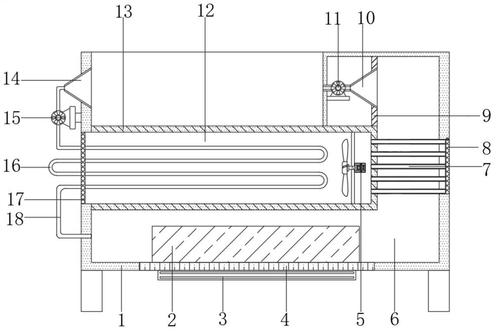
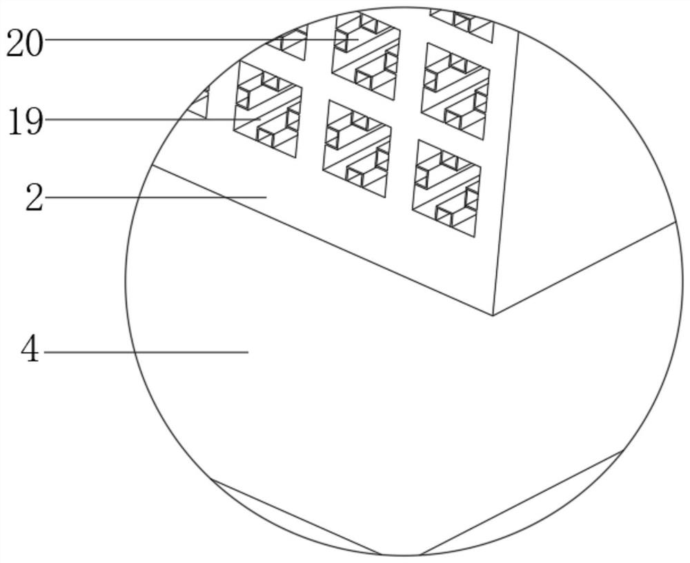
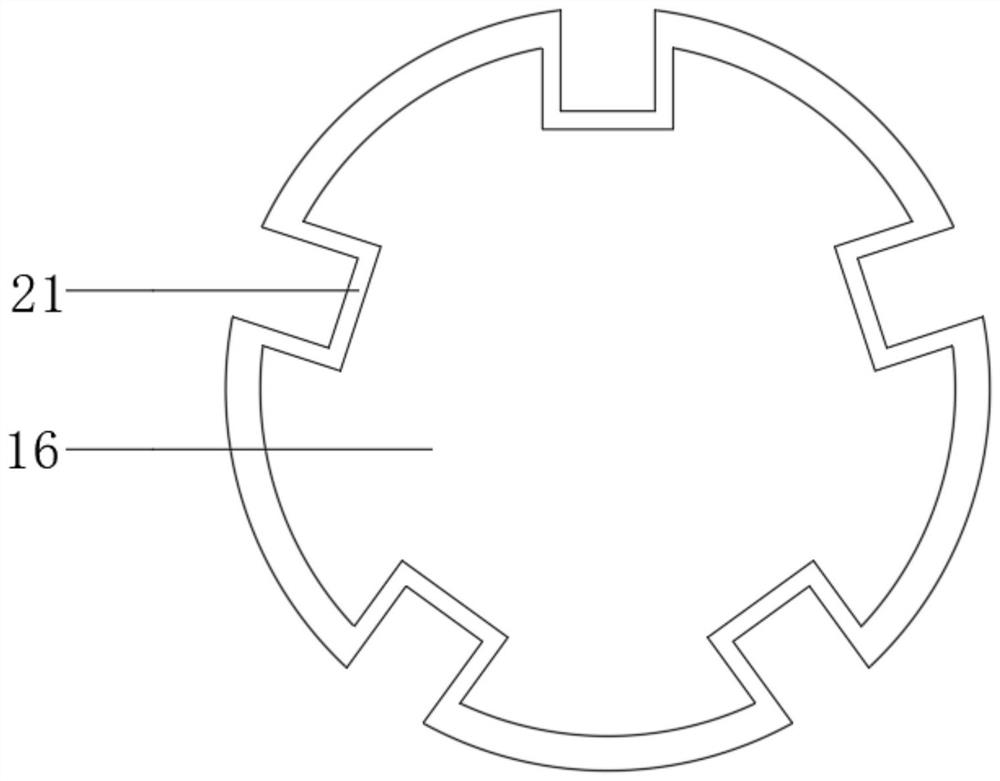
[0030] Reference Figure 1-4 , A pump body forming cooling device for the production of electromechanical equipment, comprising a main body 1 with legs welded on the four corners of the bottom outer wall, a U-shaped plate 13 is welded on one inner wall of the main body 1, and the main body 1 is open on the side close to the U-shaped plate 13 There is a heat dissipation port, the top of the main body 1 and the opposite side of the U-shaped plate 13 constitute a molding cavity, and the inner bottom of the main body 1 and the opposite side of the U-shaped plate 13 constitute a cooling end 6, and the bottom end of the cooling end 6 is provided with a mounting groove. And the inner wall of the installation groove is welded with a heat-conducting plate base 4, the bottom outer wall of the heat-conducting plate base 4 is fixed with a semiconductor refrigerator 3 by screws, and the top outer wall of the heat-conducting plate base 4 is welded with a heat exchange end 2, and the heat exch...

Embodiment 2

[0041] Reference Figure 5 , A pump body forming cooling device for the production of electromechanical equipment. Compared with the first embodiment, this embodiment also includes that one side outer wall of the rectangular branch pipe 20 is welded with a connecting piece 23, and the ends of the corresponding connecting piece 23 are welded with Two to three annular rings 22.

[0042] When the present invention is used, the arrangement of the connecting piece 23 and the annular ring 22 is used to further increase the contact heat exchange area between the heat exchange end 2 and the cooling liquid, thereby further improving the cooling effect of the cooling liquid and ensuring the cooling molding efficiency of the pump body.


PUM


Abstract

The invention belongs to the technical field of pump body cooling and molding, and particularly discloses a pump body molding and cooling device for production of electromechanical equipment. Aiming at the problems that most of traditional pump body cooling and molding devices have simple structures, the temperature of a coolant can slowly increase with the cooling and molding operation, and the molding effect is affected, the following scheme is proposed. The pump body molding and cooling device comprises a main body with supporting legs welded to four corners of the bottom outer wall, a U-shaped plate is welded to the inner wall of one side of the main body, a heat dissipation port is formed in the side, close to the U-shaped plate, of the main body, a molding cavity is formed by the topend of the main body and the opposite side of the U-shaped plate, a cooling end is formed by the inner bottom of the main body and the opposite side of the U-shaped plate, and an installation grooveis formed in the bottom end of the cooling end. According to the pump body molding and cooling device, through the mutual matching of a heat conductive plate seat, a heat exchange water channel and arectangular branch pipe, the contact area between a heat exchange end and a coolant can be effectively increased, the heat exchange area is increased, thus the cooling effect of the coolant is improved, and the cooling effect of the device on a pump body is ensured.

Description

Technical field [0001] The invention relates to the technical field of pump body cooling molding, in particular to a pump body molding cooling device for electromechanical equipment production. Background technique [0002] Electromechanical equipment generally refers to machinery, electrical appliances, and electrical automation equipment. In construction, it refers to machinery and pipeline equipment other than geotechnical, carpentry, steel, and muddy water. With the continuous improvement of people's living standards, people have more and more demand for electromechanical equipment in their daily lives. From transportation to various household appliances, computers, printers, etc., they have become indispensable electromechanical products in people's lives. Advanced electromechanical equipment can greatly increase labor productivity, reduce labor intensity, improve the production environment, and complete tasks that cannot be completed by human resources. It has a direct and ...

Claims


Application Information

Patent Timeline
Patent Type & Authority Applications(China)
IPC IPC(8): B21K29/00C21D1/64C21D9/00
CPCB21K29/00C21D1/64C21D9/0068
Inventor 郭守维
Owner 烟台福慧智能科技有限公司
Learn More