Motor-driven braided fabric pulling device and pulling method thereof

A pulling device and motor-driven technology, which is applied in weft knitting, knitting, textiles and papermaking, etc., can solve the problem of the inability to pull a single layer of cloth, the inability to achieve precise control of the pulling force, and the inability to achieve partial knitting of knitted fabrics. Pulling and other issues, to achieve the effect of reducing energy and material loss, simple and flexible structure, easy repair and maintenance

Pending Publication Date: 2020-09-18
浙江桐泰智能科技有限公司
View PDF0 Cites 7 Cited by
  • Summary
  • Abstract
  • Description
  • Claims
  • Application Information

AI Technical Summary

Problems solved by technology

[0002] At present, most of the pulling devices of knitting machines use roller devices, but the roller devices pull the braided fabric at the same time as a whole rotating motion. The pulling force depends on the rotation speed of the rollers and the surface friction of the rubber layer of the rollers, which cannot be realized. Precise control of pulling force, not to mention selective partial pulling of braids
Moreover, the rubber layer in the roller has a certain weariness, and the braid will be easily deformed when pulled to a certain extent, which increases the scrap rate
Especially on knitting, wearable and fully formed machines, because the two layers of cloth are clamped in the rollers at the same time, the pulling of a single layer of cloth cannot be realized, and the partial pulling of the cloth cannot be realized, so it cannot be used

Method used


Image

  • Motor-driven braided fabric pulling device and pulling method thereof
  • Motor-driven braided fabric pulling device and pulling method thereof
  • Motor-driven braided fabric pulling device and pulling method thereof

Examples


Embodiment 1

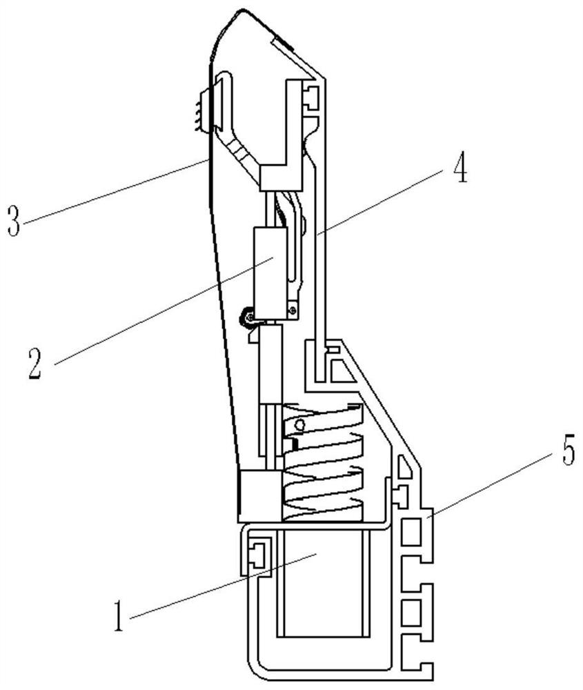
[0031] like Figure 1-7 As shown, the present invention provides a motor-driven braid pulling device, a motor-driven braid pulling device, including a housing, the housing includes an upper housing 4 and a lower housing 5, a drive module 1, And the lifting module 2. The driving module and the lifting module are respectively connected to the housing, and the driving module is driven by the motor 11 to rotate the cylindrical cam 13, and a thread groove is provided on the surface of the cylindrical cam; the lower end of the lifting module is provided with a pull rod roller 30, and the pull rod roller is arranged on the thread groove of the cylindrical cam Inside, it moves up and down with the positive and negative rotation of the cylindrical cam, thereby driving the needle claw seat 22 at the upper end of the lifting module to move up and down.

[0032] Using the cylindrical cam 13 to drive the pull rod roller to move up and down, can use the simplest mechanical structure in a l...

Embodiment 2

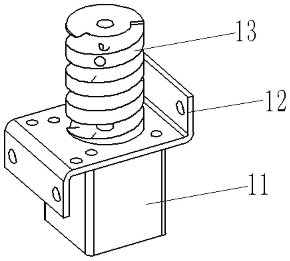
[0036] figure 2 It is a structural schematic diagram of the drive module in the embodiment of the present invention. As shown in Figures 1 and 2, the drive module is sequentially connected by a motor 11, a motor plate 12 and a cylindrical cam 13 from bottom to top, and the motor plate 12 is fixed on the lower casing 5. The motor The shaft passes above the motor plate 12, and the cylindrical cam 13 is fixed on the motor shaft. The rod roller 30 is arranged in the thread groove of the cylindrical cam 13 and moves up and down with the rotation of the cylindrical cam 13 .

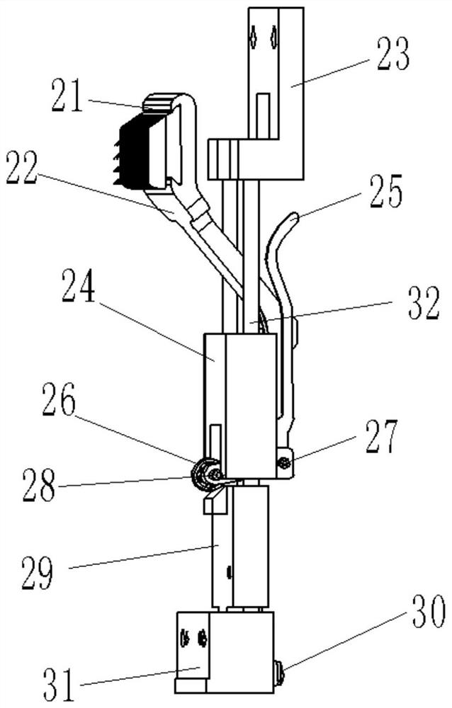
[0037] image 3 It is a schematic diagram of the lifting module of the present invention, such as image 3 As shown, the lifting module includes a lower fixed block 31, a push block 29, a guide shaft 32, and an upper fixed seat 23 connected sequentially from bottom to top. The cylindrical cam is connected to the side of the lower fixed block, and the needle claw seat is connected to the guide shaft.

[0038...

Embodiment 3

[0042] like Figure 5 , 6 As shown, the invention provides a pulling method of a braided pulling device, comprising the following steps:

[0043] Step 1: From station a to station b, the motor drives the cylindrical cam to rotate forward, and the pull rod roller moves downward in the thread groove, driving the push block to move downward along the guide shaft. The lifting seat does not have the support of the push block. The guide shaft falls, thereby driving the needle claw seat and the spring piece to move downward. The spring piece is squeezed by the protrusion of the upper shell, and moves inward to squeeze the needle claw seat. The cloth hook protrudes out of the baffle, and when the top of the spring leaf moves down to the highest point of the upper casing, the pulling device moves to the b station, and the needle claw on the cloth hook penetrates the cloth and pulls it downward;

[0044] Step 2 From station b to station c, the motor continues to drive the cylindrical ...


PUM


Abstract

The invention provides a motor-driven braided fabric pulling device and a pulling method thereof. The motor-driven braided fabric pulling device comprises a housing, a drive module and a lifting module, wherein the drive module and the lifting module are separately connected on the housing; the drive module drives a cylindrical cam to rotate through a motor; a threaded slot is formed in the surface of the cylindrical cam; the lower end of the lifting module is provided with a pulling rod roller; the pulling rod roller is arranged in the threaded slot of the cylindrical cam, and moves up and down along with positive and negative rotation of the cylindrical cam, so that a needle claw base at the upper end of the lifting module is driven to move up and down; and the head end of the needle claw base is connected to a cloth grabbing hook which moves to accomplish pulling of fabric. The pulling device provided by the invention can pull any position of braided fabric, and precisely controls and regulates pulling force; and single motor rotates to drive the cylindrical cam to drive the pulling device to operate, so that power configuration of the whole pulling device is reduced, and therefore, loss of energy and materials is reduced.

Description

technical field [0001] The invention relates to the technical field of computerized flat knitting machines, in particular to a motor-driven braided fabric pulling device and a pulling method thereof. Background technique [0002] At present, most of the pulling devices of knitting machines use roller devices, but the roller devices pull the braided fabric at the same time as a whole rotating motion. The pulling force depends on the rotation speed of the rollers and the surface friction of the rubber layer of the rollers, which cannot be realized. The pulling force is precisely controlled, and selective partial pulling of the braid cannot be realized. Moreover, the rubber layer in the roller has a certain weariness, and the braid will be easily deformed when pulled to a certain extent, which increases the reject rate. Especially on the knitting and wearing and fully formed machines, the pulling of a single layer of cloth cannot be realized due to the simultaneous clamping of...

Claims


Application Information

Patent Timeline
Patent Type & Authority Applications(China)
IPC IPC(8): D04B15/90
CPCD04B15/90
Inventor 蒋瑞荣李祥才潘加饼肖祥能李先彦
Owner 浙江桐泰智能科技有限公司
Why Eureka
Try Eureka