Fully-soluble bridge plug

A bridge plug and tie rod technology, applied in the field of fully soluble bridge plugs, can solve problems such as unstable occlusion and uneven slippage, and achieve the effect of avoiding waste.

Pending Publication Date: 2020-09-18
四机赛瓦石油钻采设备有限公司
View PDF1 Cites 5 Cited by
  • Summary
  • Abstract
  • Description
  • Claims
  • Application Information

AI Technical Summary

Problems solved by technology

[0006] Aiming at the deficiencies of the prior art, the present invention provides a fully soluble bridge plug, which has the advantages of facilitating the uniform rupture of slips and stable occlusal, and solves the problem of incompatibility of the existing fully soluble bridge plug during use. The problem of stability, and the problem that the slips are not uniform enough

Method used


Image

  • Fully-soluble bridge plug
  • Fully-soluble bridge plug
  • Fully-soluble bridge plug

Examples


Embodiment 1

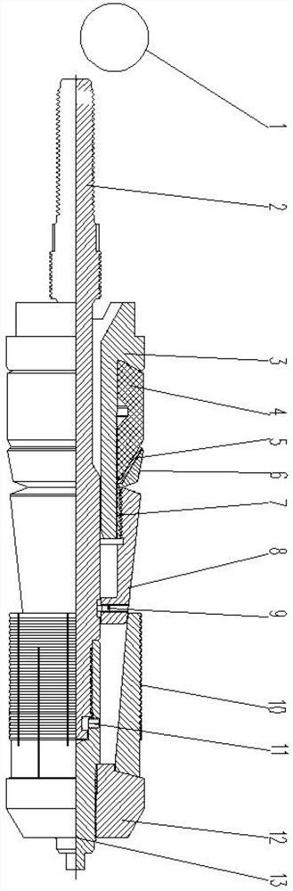
[0039] see figure 1 , 2 , 3, 4, 8, a fully soluble bridge plug includes a soluble ball 1, a central tube 3, a rubber tube 4, a back ring, a cone 8, a lock ring 7, slips 10 and guide shoes 12, and a shear rod 13 is fixedly connected to the lower end of the pull rod 2 by at least one fastening screw 11, the pull rod 12 and the shear rod 13 are made of alloy steel, and the central tube 3, the rubber tube 4, the back ring and the slip 10 are all installed and restricted On the tie rod 2 and the shear rod 13, the upper end of the tie rod 2 is connected with the setting tool through threads; the bridge plug setting is to seal the casing in the well. 13 will be taken out of the wellhead with the setting tool, and will not leave insoluble alloys in the well.

[0040] Two observation grooves 14 are milled on the upper end of the central tube 3, which can be used to observe whether the guide joint in the adapter is installed in place. The inner hole at the upper end of the central tub...

Embodiment 2

[0048] Such as Figure 5 , 6 , 7, the difference from Embodiment 1 is that the difference between the first structure and the second structure is as follows:

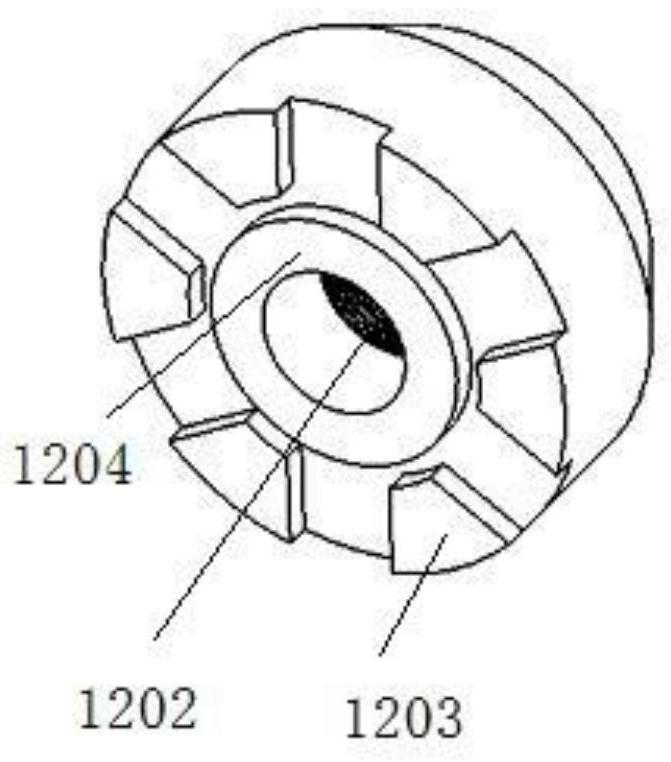
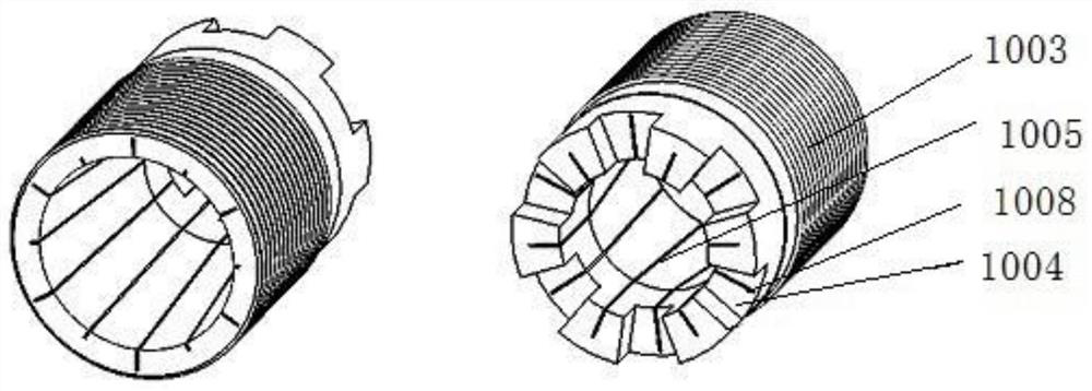
[0049] The first structure is an upper cone surface and a lower cone surface 1201 that match up and down. The upper cone surface is arranged at the lower end of the slip 10, and a circular step 1204 is provided at the upper end of the guide shoe 12; the lower cone surface 1201 is arranged at the bottom of the guide shoe 12 The upper end is located around the circular step; the upper conical surface is a 15° conical surface, which is convenient for the slips 10 to be deformed by the shoe 12 during setting and evenly opened; the upper conical surface of the slips 10 is axially circumferential The number of six third slots 1007 is distributed, and the upper end surface of the slip 10 is distributed with a number of six fourth slots 1001 on the axial circumference, and the fourth slots 1001 and the third slots 1007 are dis...


PUM


Abstract

The invention relates to the technical field of petroleum development downhole tools, and discloses a fully-soluble bridge plug. The fully-soluble bridge plug comprises a pull rod and a shear rod, wherein the shear rod is fixedly connected to the lower end of the pull rod through at least one fastening screw, the pull rod is sleeved with a central pipe, the outer surface of the lower end of the central pipe is connected with a one-way moving cone through a locking ring, a rubber sleeve is arranged between the outer surface of the central pipe and the upper end of the cone, the lower end of thecone is connected to the pull rod through a shear pin, the lower end of the shear rod is in threaded connection with a guiding shoe, and slips capable of being connected with the cone in an insertedmode are arranged on the guiding shoe. According to the fully-soluble bridge plug, through matching of the structures formed between the slips and the guiding shoe, the slips can be evenly broken whenbeing engaged with a casing pipe, and the risk that the bridge plug is not centered in the casing pipe due to the fact that the axial positions of the slips are not uniform or the slips are broken from a certain position to form a larger notch, and finally bridge plug anchoring is unreliable is avoided.

Description

technical field [0001] The invention relates to the technical field of oil development downhole tools, in particular to a fully soluble bridge plug. Background technique [0002] At present, the staged fracturing of unconventional oil and gas is mainly based on the staged fracturing of the composite bridge plug. After the composite bridge plug is completed, it is necessary to drill and grind the bridge plug with coiled tubing. The operation time of the coiled tubing equipment is long and the cost is high. There are also operational risks such as coiled tubing self-locking, drill sticking, and tool falling into the well. With the exploration and development of deep shale gas, it becomes more difficult for coiled tubing to drill composite bridge plugs in long horizontal well sections. [0003] Application number is 201810136992.9, a single-slip fully soluble bridge plug, a single-slip fully soluble bridge plug, including a central tube, a fracturing ball, a sliding sleeve, a ...

Claims


Application Information

Patent Timeline
Patent Type & Authority Applications(China)
IPC IPC(8): E21B33/134
CPCE21B33/134
Inventor 王传鸿邹刚周歆杨小城余修明
Owner 四机赛瓦石油钻采设备有限公司
Why Eureka
Try Eureka