Fluid mechanics simulation method and device and storage medium

A fluid mechanics and flow field technology, applied in the field of fluid mechanics simulation, which can solve the problems of complex simulation program, difficult fluid calculation, and large amount of calculation.

Pending Publication Date: 2020-09-18
SHENZHEN INST OF ADVANCED TECH CHINESE ACAD OF SCI
View PDF3 Cites 12 Cited by
  • Summary
  • Abstract
  • Description
  • Claims
  • Application Information

AI Technical Summary

Problems solved by technology

[0003] In the prior art, in order to solve the problems of stability, convergence speed, and parallel efficiency in the macroscopic continuous model in the prior art, and the simulation program in the microscopic molecular model is more complex, the amount of calculation is large, and the requirements for memory For advanced problems, the lattice Boltzmann method can be used to numerically simulate and solve more complex flow field problems
Specifically, the lattice Boltzmann method mostly uses uniform Cartesian grids, but for geometric models with complex boundaries, the number of grids required is often huge
Due to the defects of the uniform Cartesian grid, the lattice Boltzmann method is difficult to deal with fluid calculations with complex geometric boundaries, so a technical solution that can solve the above technical problems is needed

Method used


Image

  • Fluid mechanics simulation method and device and storage medium
  • Fluid mechanics simulation method and device and storage medium
  • Fluid mechanics simulation method and device and storage medium

Examples


no. 2 example K2

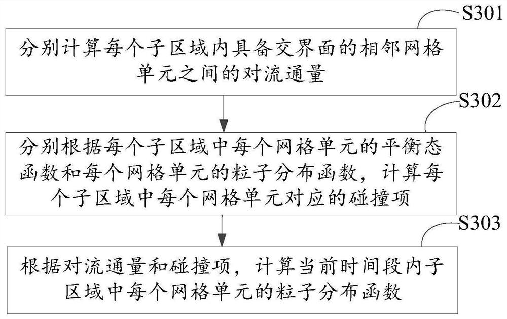
[0104] Among them, A α,i is the convective flux between adjacent grid cells with interfaces in the sub-region, C α,i is the collision item corresponding to the grid cell in the sub-region.

[0105] After obtaining the first proportion K respectively 1 and the second ratio K 2 After that, calculate the particle distribution function of each grid cell in the sub-area in the current time period according to the following calculation formula:

[0106]

[0107] in, is the particle distribution function of the sub-region in the time period t+Δt, is the particle distribution function of the sub-region in the time period t.

[0108] See Figure 4 , Figure 4 It is a schematic flowchart of another embodiment of a fluid dynamics simulation method in the present application. In the current embodiment, what is highlighted is the further step of determining the macroscopic information corresponding to the grid units in each sub-area according to the particle distribution funct...


PUM


Abstract

The invention discloses a fluid mechanics simulation method and device and a storage medium, and the method comprises the steps: obtaining a flow field model, and generating a flow field grid; obtaining initial macroscopic information, boundary condition information and the number of execution processes which are set based on the flow field model; dividing the flow field grid to obtain a pluralityof subareas corresponding to the number of executed processes, and allocating a corresponding subarea to each process; calculating a particle distribution function corresponding to each grid unit ineach subarea by utilizing each process, and determining macroscopic information corresponding to the grid unit in each subarea according to the particle distribution function of the grid unit in eachsubarea; calculating a convergence value of the flow field according to the macroscopic information of the grid units in the subareas, and judging whether the flow field model meets a convergence condition or not according to the convergence value of the flow field; and aggregating the macroscopic information of the grid units in each sub-region and outputting the aggregated macroscopic information as a simulation result of the flow field model, thereby realizing simulation calculation of a large-scale complex flow field.

Description

technical field [0001] The present application relates to the technical field of fluid mechanics, in particular to a method, device and storage medium for fluid mechanics simulation. Background technique [0002] Fluid mechanics is one of the scientific disciplines gradually formed in human society from practical activities. With the emergence and development of computer technology, numerical calculation methods have become one of the three important scientific research methods alongside theoretical analysis and experimental research. Numerical simulation of complex flow fields in computational fluid dynamics is closely related to national development, social progress and human life. Through numerical calculation methods combined with high-performance computing technology, many complex flow field problems can be numerically simulated and solved, which can save the cost of physical experiments to a certain extent and speed up the research progress. [0003] In the prior art...

Claims


Application Information

Patent Timeline
Patent Type & Authority Applications(China)
IPC IPC(8): G06F30/28G06F30/25G06F113/08G06F119/14
CPCG06F30/28G06F30/25G06F2113/08G06F2119/14
Inventor 徐磊陈荣亮古林燕许文馨闫争争蔡小川
Owner SHENZHEN INST OF ADVANCED TECH CHINESE ACAD OF SCI
Why Eureka
Try Eureka