A 3d-mimo adjustable antenna

A 3D-MIMO, adjustable technology, applied to antenna arrays, antennas, diversity/multi-antenna systems that are powered on separately, can solve the problems of high cost of signal receiving modules, inability to adjust spatial dimensions, single function, etc., to achieve signal reception Wide range, diverse functions, good signal reception effect

Active Publication Date: 2021-05-25
上海东洲罗顿通信股份有限公司
View PDF5 Cites 0 Cited by
  • Summary
  • Abstract
  • Description
  • Claims
  • Application Information

AI Technical Summary

Problems solved by technology

[0005] Based on the existing technical problems of high cost of replacing the entire signal receiving module, inability to adjust the spatial dimension, and single function, the present invention proposes a 3D-MIMO dimension-adjustable antenna

Method used


Image

  • A 3d-mimo adjustable antenna
  • A 3d-mimo adjustable antenna
  • A 3d-mimo adjustable antenna

Examples


Embodiment 1

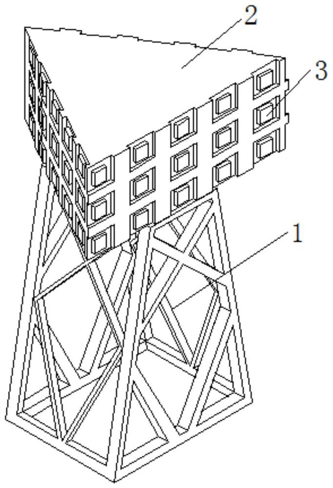
[0042] refer to Figure 1-6 , a 3D-MIMO dimension-adjustable antenna, comprising an antenna base 1, one end of the antenna base 1 is fixedly mounted with a signal receiving seat 2, the signal receiving seat 2 is a triangular structure, and the surface of the signal receiving seat 2 is provided with signal receiving mechanism.

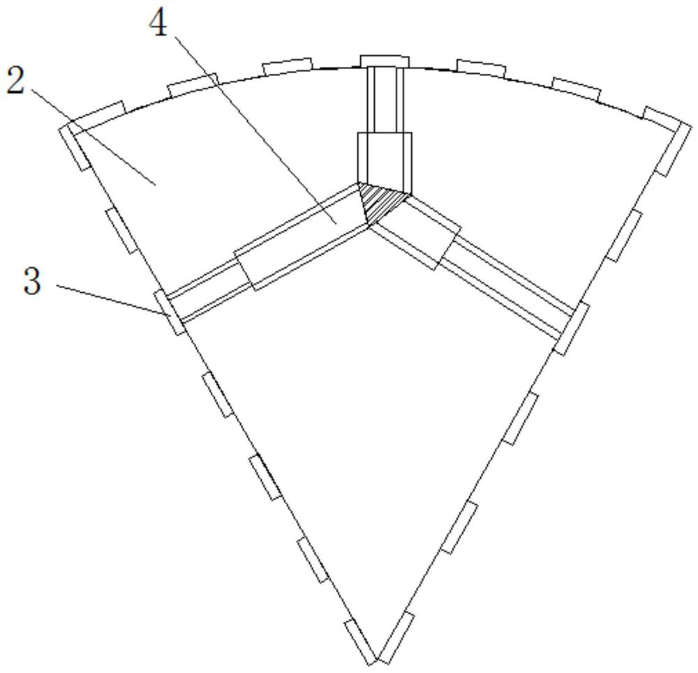
[0043]Further, the signal receiving mechanism includes an elastic module 3, and a plurality of elastic modules 3 are arrayed on the surface of the signal receiving seat 2, and among the plurality of elastic modules 3, a first hydraulic rod 4 is fixedly installed on the surface of an elastic module 3 in the middle.

[0044] Further, the surface of the elastic module 3 is movably clamped with the antenna module 5 , a plurality of antenna modules 5 are stacked layer by layer through clamping, and the surface of the antenna module 5 is coated with a wave-absorbing material.

[0045] Further, connecting bolts 6 are arranged on the sides of the elastic modul...

Embodiment 2

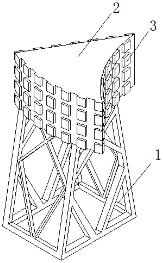
[0057] refer to Figure 1-2 and Figure 4-7 , a 3D-MIMO dimension-adjustable antenna, comprising an antenna base 1, one end of the antenna base 1 is fixedly mounted with a signal receiving seat 2, the signal receiving seat 2 is a triangular structure, and the surface of the signal receiving seat 2 is provided with signal receiving mechanism.

[0058] Further, the signal receiving mechanism includes an elastic module 3, and a plurality of elastic modules 3 are arrayed on the surface of the signal receiving seat 2, and among the plurality of elastic modules 3, a first hydraulic rod 4 is fixedly installed on the surface of an elastic module 3 in the middle.

[0059] Further, the surface of the elastic module 3 is movably clamped with the antenna module 5 , a plurality of antenna modules 5 are stacked layer by layer through clamping, and the surface of the antenna module 5 is coated with a wave-absorbing material.

[0060] Further, connecting bolts 6 are arranged on the sides of...

Embodiment 3

[0072] A 3D-MIMO dimension-adjustable antenna described in Embodiments 1 and 2 above, further, the antenna module (5) is stacked layer by layer by clamping, and the number of layers to be stacked can be determined by the following method;

[0073] First, obtain the height of the antenna module, the central operating wavelength and the power density of the signal generated by the actual antenna at a point in space;

[0074] Then calculate the estimated height;

[0075]

[0076] Among them, L is the expected height, a is the power density of the signal generated by the actual antenna at a point in space, b is the power density of the signal generated by the ideal radiating unit at the same point in space, and lg is the pair with base 10 number function, ln is a logarithmic function with e as the base, and λ is the central working wavelength;

[0077] Finally determine the number of superimposed layers;

[0078] n=int(L / h)+1

[0079] Wherein, n is the number of overlapping ...


PUM


Abstract

The invention belongs to the technical field of communication equipment, in particular to a 3D-MIMO dimension-adjustable antenna, comprising an antenna base, one end of the antenna base is fixedly mounted with a signal receiving seat, the signal receiving seat is a triangular structure, and the surface of the signal receiving seat is A signal receiving mechanism is provided. The 3D‑MIMO dimension-adjustable antenna controls the multiple first hydraulic rods to extend or contract inward through solenoid valves, and the modules gradually expand outward or inward from the middle to form an outward or inward arc. The outward expansion makes the signal reception range wider, and the inward expansion makes the signal reception more concentrated and better to receive the signal. The solenoid valve controls the second hydraulic rod to extend upward, and multiple antenna modules extend upward one by one, and multiple elastic modules are formed. In order to adjust the signal receiving dimension space for the outward trapezoidal shape, one solenoid valve in the solenoid valve group corresponds to one hydraulic rod in the hydraulic rod group, and any elastic module can be replaced and changed.

Description

technical field [0001] The invention relates to the technical field of communication equipment, in particular to a 3D-MIMO dimensionally adjustable antenna. Background technique [0002] MIMO technology refers to the ability to double the capacity and spectrum utilization of the communication system without increasing the bandwidth. It can be defined as the existence of multiple independent channels between the transmitting end and the receiving end, that is to say, between the antenna units There is sufficient separation, therefore, the correlation of the signals between the antennas is eliminated, the link performance of the signals is improved, and the data throughput is increased. [0003] On the one hand, 3D-MIMO can flexibly adjust the beam direction in the horizontal and vertical dimensions to form narrower and more precise directional beams, thereby greatly improving the energy received by terminals and enhancing cell coverage; on the other hand, 3D-MIMO can fully U...

Claims


Application Information

Patent Timeline
Patent Type & Authority Patents(China)
IPC IPC(8): H01Q21/06H01Q1/12H01Q1/36H01Q3/01H04B7/08
CPCH01Q1/12H01Q1/36H01Q3/01H01Q21/06H04B7/08
Inventor 邓双凤
Owner 上海东洲罗顿通信股份有限公司
Why Eureka
Try Eureka