Cable ground laying device

A cable and ground technology, used in the field of cable ground laying devices, can solve the problems of cable surface wear, affecting power supply reliability, cable resistance, etc., achieve good flexibility and wear resistance, avoid power supply reliability, and prevent excessive weight. Effect

Active Publication Date: 2020-09-18
南京东瑞水电工程有限公司
View PDF14 Cites 14 Cited by
  • Summary
  • Abstract
  • Description
  • Claims
  • Application Information

AI Technical Summary

Problems solved by technology

[0003] At present, when laying cables underground, it is necessary to dig a cable trench on the ground in advance, then pour concrete on the wall of the cable trench, and then lay the cable inside the cable trench. Long, thick and hard cables, and more tortuous and complicated laying paths require more manpower to drag and limit positions. Due to the heavy weight of the cables, the manpower and time spent on cable laying are greatly increased, and personnel are dragging When the cable is pulled, the cable and the bottom wall of the cable trench will generate a large friction force, which will easily cause the surface of the cable to be worn, resulting in damage to the outer sheath of the cable, and extrusion of the inner insulation tube. In severe cases, the insulation at the sheath will even be broken. The heat pipe will eventually affect the vacuum degree and mechanical properties of the cable system, affecting the reliability of power supply; at the same time, the friction between the cable and the ground will cause greater resistance to the movement of the cable, which greatly affects the construction efficiency of cable laying

Method used


Image

  • Cable ground laying device
  • Cable ground laying device
  • Cable ground laying device

Examples


Embodiment Construction

[0047] The following is attached Figure 1-11 The application is described in further detail.

[0048] The embodiment of the present application discloses a ground cable laying device.

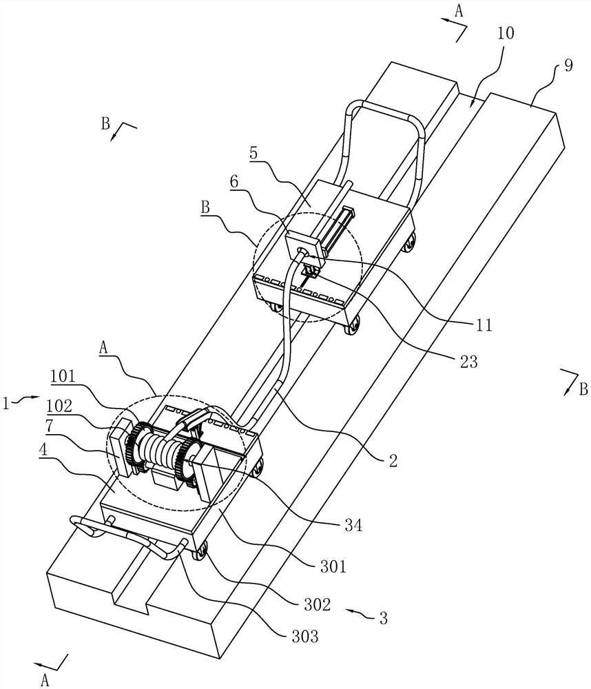
[0049] refer to figure 1 , a cable laying device on the ground, comprising two trolleys 3, a cable trench 10 is dug on the ground 9, the two trolleys 3 are erected on the ground 9, the trolley 3 is located above the cable trench 10, and the trolley 3 includes a base 301, Universal wheels 302 arranged at the four corners of the lower surface of the base 301 and hand push rods 303 arranged on the side walls of the base 301 .

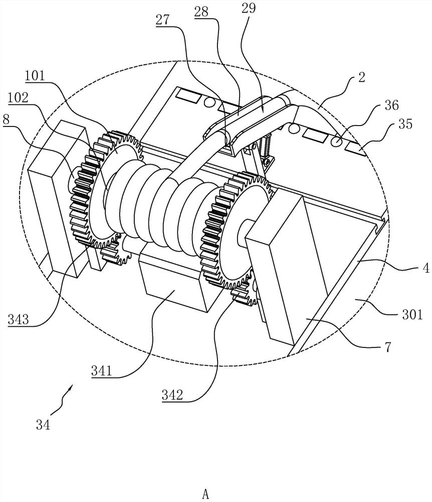
[0050] refer to figure 1 with figure 2 , the base 301 of one of the trolleys 3 is fixedly installed with a pay-off seat 4, and the upper surface of the pay-off seat 4 is provided with two relative support platforms 7, and the opposite side walls of the two support platforms 7 are all rotatably connected with mounting columns 8. A cable reel 1 is provided between the ...


PUM


Abstract

The invention relates to a cable ground laying device. The invention relates to the technical field of cable laying. The cable ground laying device comprises two trolleys which are oppositely erectedon the ground and located above a cable trench, a pay-off base and a traction base which are installed on the two trolleys respectively, a clamping table which is arranged on the traction base, two supporting tables which are oppositely arranged on the pay-off base, and installation columns which are rotationally arranged on the opposite side walls of the two supporting tables respectively. The side wall of the clamping table is provided with a fixing groove for insertion of a cable. A locking assembly used for fixing the cable is arranged in the fixing groove. An automatic receding assembly used for preventing the cable from making contact with the side wall of the traction base is arranged on the upper surface of the traction base. The two installation columns are fixedly connected withthe two side walls of two cable reels respectively, and a driving assembly used for driving the cable reels to rotate is arranged on the pay-off base. The laying device replaces manpower to drag the cable for laying, which saves time and labor, and improves the cable laying efficiency. Friction damage between the cable and the ground can be prevented, and the power supply reliability of the cableis prevented from being affected.

Description

technical field [0001] The present application relates to the technical field of cable laying, in particular to a cable ground laying device. Background technique [0002] Cable laying refers to the process of laying and installing cables along the surveyed route to form a cable line. According to the application occasion, it can be divided into several laying methods such as overhead, underground (pipeline and direct burial), underwater, wall and tunnel. The choice of cable laying method is very important to ensure the transmission quality, reliability and construction maintenance of the line. [0003] At present, when laying cables underground, it is necessary to dig a cable trench on the ground in advance, then pour concrete on the wall of the cable trench, and then lay the cable inside the cable trench. Long, thick and hard cables, and more tortuous and complicated laying paths require more manpower to drag and limit positions. Due to the heavy weight of the cables, the...

Claims


Application Information

Patent Timeline
Patent Type & Authority Applications(China)
IPC IPC(8): H02G1/06
CPCH02G1/06
Inventor 何培根孔明明
Owner 南京东瑞水电工程有限公司
Why Eureka
Try Eureka