A solar-powered drone for infrastructure

A technology of solar unmanned aerial vehicles and unmanned aerial vehicles, which is applied in the direction of motor vehicles, rotorcraft, aircraft parts, etc., can solve the problems of wire sheath wear, wire swing range, wire quality decline, etc., to achieve high efficiency and improve the landing point Accuracy, the effect of reducing wind resistance

Active Publication Date: 2021-08-17
河北柒壹壹玖工业自动化技术有限公司
View PDF7 Cites 0 Cited by
  • Summary
  • Abstract
  • Description
  • Claims
  • Application Information

AI Technical Summary

Problems solved by technology

[0003] Traditional drones are divided into two working environments when performing work. One is to simply fix the wires with tape or other tools and the traction rope, and then hang the upper end of the traction rope under the drone for traction. This operation wire itself The distance between the UAV and the UAV is relatively large. Due to the influence of the surrounding environment, the wire swings a lot, so that the UAV cannot fly stably, and the accuracy error of the wire landing point is relatively large; the second is to install it under the UAV. The traditional fixing clip fixes the wire through the fixing clip, and the operating fixing clip is completely fixed with the wire. When the UAV has a small angle change, the fixing clip will generate a knob force on the wire, and the reaction force of the wire will make the drone unmanned. The flight of the aircraft is greatly affected. The traditional fixing method cannot offset the knob force generated by the wire. When the knob force is greater than the friction force between the fixing clip and the wire, there will be relative movement between them, which will cause the wire sheath to wear and tear the wire. The quality of the wires has declined; in addition, the transmission clips are basically exposed outside, which will generate greater resistance when the UAV is flying at high speed, thereby increasing the energy consumption of the UAV

Method used


Image

  • A solar-powered drone for infrastructure
  • A solar-powered drone for infrastructure
  • A solar-powered drone for infrastructure

Examples


Embodiment Construction

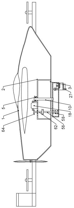
[0034] The present invention is specifically described below in conjunction with accompanying drawing, as Figure 1-15 As shown, a solar unmanned aerial vehicle for infrastructure construction includes a composite wing unmanned aerial vehicle 1, the lower end of the composite wing unmanned aerial vehicle 1 is provided with a reciprocating lifting mechanism, and the lower end of the reciprocating lifting mechanism is provided with a clamping and releasing mechanism. There is a linkage transmission mechanism on one side of the release mechanism;

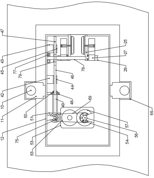
[0035]The reciprocating lifting mechanism includes a rectangular box 2 on the lower surface of the composite wing UAV 1, the lower surface of the rectangular box 2 has a rectangular opening 3, and the upper surface of the rectangular box 2 has a through hole 4, and the through hole 4 is provided with two A fixed ring 5 is installed on one side of the through hole 4, a roller bearing 6 is installed on the upper end of the fixed ring 5, ...


PUM


Abstract

The invention discloses a solar-powered unmanned aerial vehicle for infrastructure construction, including a compound-wing unmanned aerial vehicle. The lower end of the composite-wing unmanned aerial vehicle is provided with a reciprocating lifting mechanism, and the lower end of the reciprocating lifting mechanism is provided with a clamping and releasing mechanism. One side of the clamping release mechanism is provided with a linkage transmission mechanism. The beneficial effect of the present invention is that the electric wire can be stably fixed on the drone through the action of the clamping and releasing mechanism, and the relative movement between the clamp and the electric wire can be effectively avoided through its fixing method, and the accuracy of the landing point of the electric wire is improved, so that Its work is more efficient; through the function of the reciprocating lifting mechanism, the clamp can be shrunk into the inside of the drone when not in use, so as to reduce the effect of wind resistance.

Description

technical field [0001] The invention relates to the technical field of unmanned aerial vehicle power wiring, and more specifically, relates to a solar unmanned aerial vehicle used for infrastructure construction. Background technique [0002] In the power line operation, the UAV can also give full play to its characteristics of flexible flight and simple operation. After the UAV is equipped with special power line inspection equipment, it can perform line inspection operations on power lines in mountains, canyons and other areas; The human-machine power line inspection system has high work efficiency, which greatly reduces the cost of power line inspection; [0003] Traditional drones are divided into two working environments when performing work. One is to simply fix the wires with tape or other tools and the traction rope, and then hang the upper end of the traction rope under the drone for traction. This operation wire itself The distance between the UAV and the UAV is r...

Claims


Application Information

Patent Timeline
Patent Type & Authority Patents(China)
IPC IPC(8): B64C39/02B64C27/22B64D1/00H02G1/02
CPCB64C27/22B64C39/02B64D1/00H02G1/02
Inventor 李洁
Owner 河北柒壹壹玖工业自动化技术有限公司
Why Eureka
Try Eureka