A slope anchoring device for municipal engineering

An anchoring device and engineering technology, which is applied in basic structure engineering, construction, excavation, etc., can solve the problems that the needles cannot reach the expected insertion depth and affect the anchoring effect of the anchoring support device, etc., and achieve the effect of simple structure

Active Publication Date: 2021-08-27
北京欣江峰市政工程有限责任公司
View PDF1 Cites 0 Cited by
  • Summary
  • Abstract
  • Description
  • Claims
  • Application Information

AI Technical Summary

Problems solved by technology

[0004] The above-mentioned existing technical solutions have the following defects: when the needle is pushed out by the force bar to be inserted into the soil of the slope, if the needle is pushed out and blocked by hard objects such as stones, the needle will It is difficult to continue to push out under the action of the force bar; since the needles on the same side are all located on the same vertical main bar, when one of the needles is blocked, all the needles on the same vertical bar cannot achieve the desired result The insertion depth affects the anchoring effect of the anchor support device

Method used


Image

  • A slope anchoring device for municipal engineering
  • A slope anchoring device for municipal engineering
  • A slope anchoring device for municipal engineering

Examples


Embodiment 1

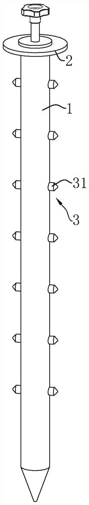
[0039] refer to figure 1, the present invention discloses a slope anchoring device for municipal engineering, which includes an anchor pipe 1 pierced into the slope ground, and the anchor pipe 1 is an oblong pipe body with a hollow inner cavity and an open top. In order to facilitate the insertion of the anchor tube 1, the bottom end of the anchor tube 1 is set as a tip. An anchor pipe fixing plate 2 for abutting against the slope ground is fixedly connected to the outer peripheral surface of the top end of the anchor pipe 1 .

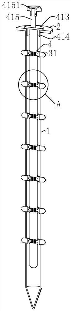
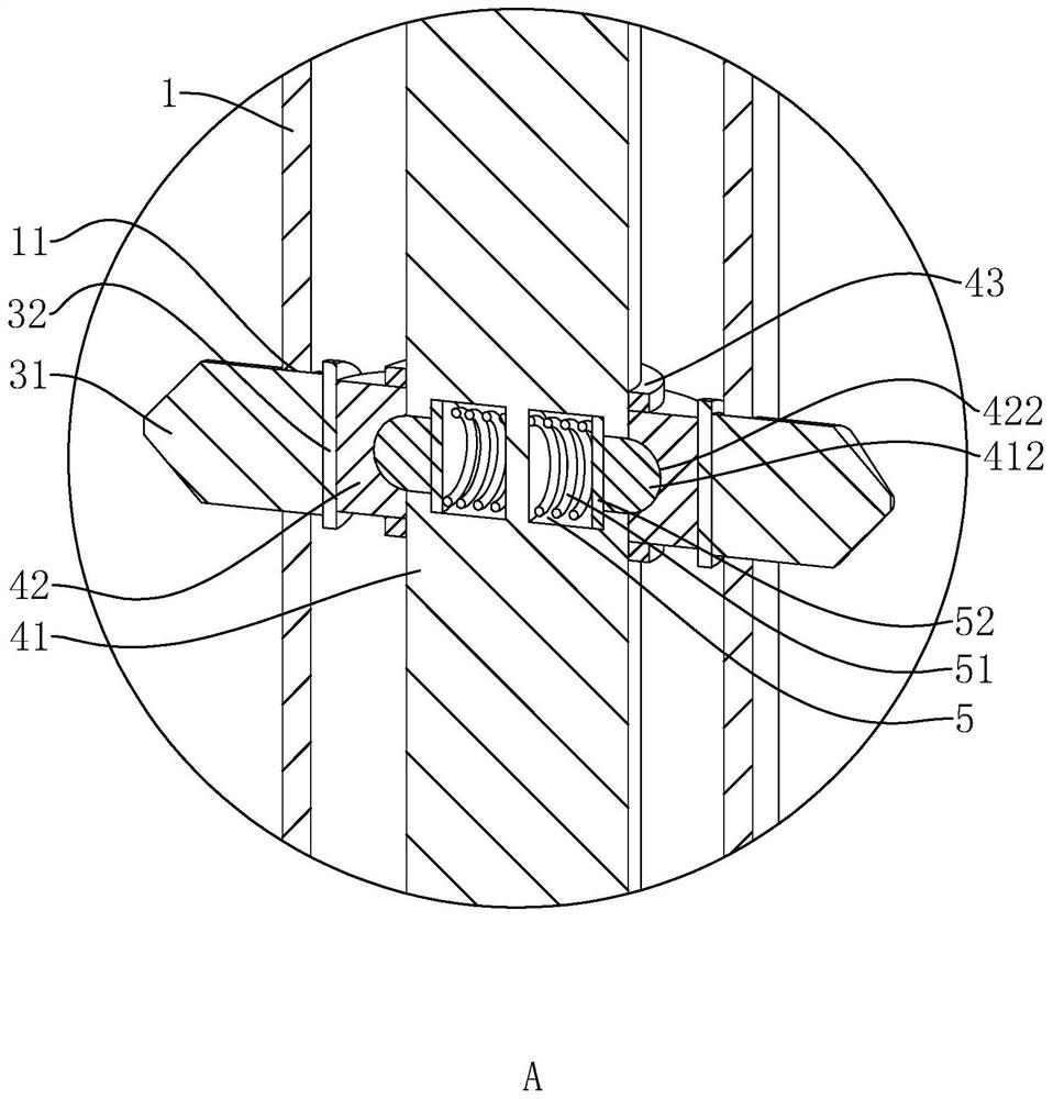
[0040] refer to figure 2 and image 3 The anchor tube 1 is provided with multiple sets of needle assemblies 3 at intervals along its axial direction, each group of needle assemblies 3 includes a plurality of needles 31 uniformly distributed along the circumferential direction of the anchor tube 1, the needles 31 are arranged radially along the anchor tube 1, and the needles 31 The end facing away from the lumen of the anchor tube 1 is the tip. The...

Embodiment 2

[0051] The difference from Embodiment 1 is that, referring to Figure 5 The slot 422 is provided on the inner side of the cam 42 away from the edge of the anchor tube fixing plate 2. The slot 422 is a quarter arc-shaped slot that runs through the inner peripheral surface of the cam 42 and the end surface adjacent to the above-mentioned edge. The slot 422 at the edge is convenient for the staff to process it.

[0052] One end of the snap-in rod 412 away from the force-applying rod 41 extends into the slot 422, and the end surface of the snap-in rod 412 facing the slot 422 abuts against the inner peripheral wall of the slot 422, and the snap-in rod 412 contacts the slot during the movement. The abutting surface of 422 is an arc surface.

[0053] The locking groove 422 can also be opened on the inner side of the cam 42 close to the edge of the anchor tube fixing plate 2, and the effect is the same as that of this embodiment.

Embodiment 3

[0055] The difference from Embodiment 1 is that, referring to Figure 6 and Figure 7 The force applying rod 41 is provided with a pressing assembly capable of pressing one end of the clamping rod 412 against the clamping groove 422. The pressing assembly includes a receiving groove 6 opened on the applying rod 41, and the receiving groove 6 is a The long groove that force rod 41 is axially arranged, the setting of accommodating groove 6 makes force application rod 41 form the hollow hollow pipe body of inner hollow, and force application rod 41 is closed along the two ends of self axial direction, and force application rod 41 top is provided with and accommodates. The one-way valve 61 connected to the cavity of the tank 6 is filled with high-pressure air in the tank 6 .

[0056] A dynamic sealing ring 4111 is fixedly connected to the inner peripheral surface of the sliding groove 411 , and the inner peripheral surface of the dynamic sealing ring 4111 abuts against the outer ...


PUM


Abstract

The invention discloses a side slope anchoring device for municipal engineering, and relates to the technical field of side slope anchoring. The force application mechanism includes a force application rod coaxially arranged in the anchor pipe, the force application rod is sleeved with a plurality of cams for pushing out the puncture needle, and the force application rod is provided with a cam for preventing the cam from being along the axial direction of the force application rod. The moving limit component; the cam is provided with a clamping slot, the force applying rod is connected with a clamping rod along its radial direction sliding, and one end of the clamping rod is abutted on the inner wall of the clamping slot; the force application rod is provided with an energy One end of the clamping rod is pressed against the abutting component in the clamping slot, and the clamping rod can be disengaged from the clamping groove, so that the cam and the force applying rod are in a state of relative rotation. In the present invention, when the lancet in some lancet assemblies on the anchor tube is blocked and cannot be pushed out further, other groups of lancet assemblies can be pushed out to the desired depth, which ensures the anchoring effect of the anchoring device.

Description

technical field [0001] The invention relates to the technical field of slope anchoring, in particular to a slope anchoring device for municipal engineering. Background technique [0002] Municipal engineering refers to the construction of various public infrastructure supporting urban life, such as urban roads, bridges, subways, etc. In the construction process of municipal engineering construction, for most rock and soil slopes, anchoring technology is usually used to reinforce the slope to avoid disastrous factors such as landslides, sideslips, and collapses of the slope. Among various anchoring measures, prestressed anchors are the most widely used. This kind of reinforcement method is to strengthen the rock and soil mass or improve the internal stress state by applying prestressed tension to the anchor to achieve the purpose of reinforcement. [0003] The Chinese invention patent with the authorized notification number CN106120821B discloses an ingrown root anchor suppo...

Claims


Application Information

Patent Timeline
Patent Type & Authority Patents(China)
IPC IPC(8): E02D17/20E02D5/76
CPCE02D5/76E02D17/207Y02A10/23
Inventor 赵德源张维昌闫开珍王争
Owner 北京欣江峰市政工程有限责任公司
Why Eureka
Try Eureka