
Anti-blocking energy-saving building rainwater self-collecting device based on rainwater potential energy driving

A collection device and anti-blocking technology, which is applied in the field of rainwater self-collecting devices for anti-blocking energy-saving buildings, can solve the problems of blockage of the rainwater collection device, poor rainwater purification effect, affecting the cleanliness of the rainwater collection device, etc., to improve the purification effect. , Improve the effect of cleanliness

Active Publication Date: 2020-09-22
武汉博安建设工程有限公司
View PDF6 Cites 6 Cited by
  • Summary
  • Abstract
  • Description
  • Claims
  • Application Information

AI Technical Summary

Problems solved by technology

[0007] The object of the present invention is to provide an anti-blocking energy-saving rainwater self-collection device for buildings driven by rainwater potential energy to solve the above-mentioned background technology. , it is easy to accumulate inside the rainwater collection device due to falling leaves or debris from the outside, which will affect the overall cleanliness of the rainwater collection device. Rainwater will easily carry some impurities such as fallen leaves accumulated on the roof and fall into the rainwater collection device. The inside of the device, so that after a long period of use, the fallen leaves mixed in the rainwater will easily cause the blockage of the rainwater collection device. Problems with the practicality of collection devices

Method used


Image

  • Anti-blocking energy-saving building rainwater self-collecting device based on rainwater potential energy driving
  • Anti-blocking energy-saving building rainwater self-collecting device based on rainwater potential energy driving
  • Anti-blocking energy-saving building rainwater self-collecting device based on rainwater potential energy driving

Examples


Embodiment Construction

[0032] The following will clearly and completely describe the technical solutions in the embodiments of the present invention with reference to the accompanying drawings in the embodiments of the present invention. Obviously, the described embodiments are only some, not all, embodiments of the present invention. Based on the embodiments of the present invention, all other embodiments obtained by persons of ordinary skill in the art without making creative efforts belong to the protection scope of the present invention.

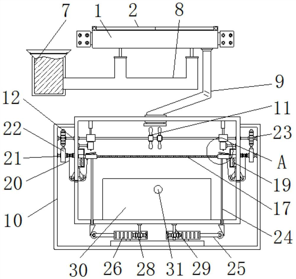
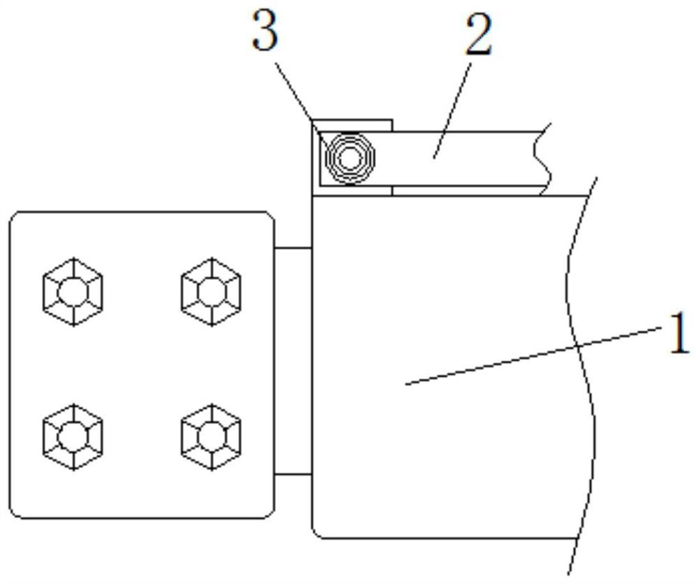
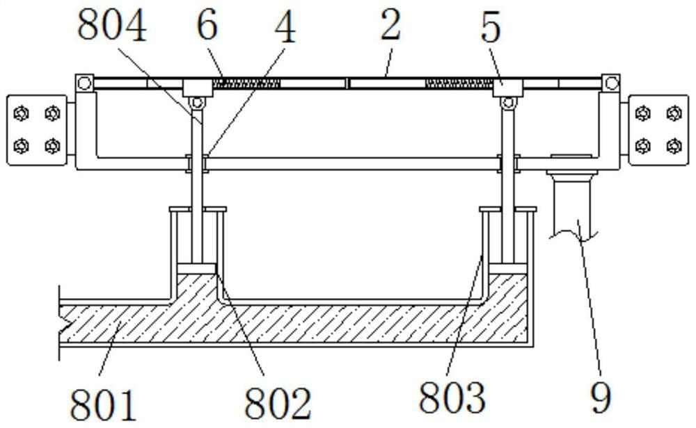
[0033] see Figure 1-9, the present invention provides a technical solution: an anti-blocking energy-saving building rainwater self-collection device driven by rainwater potential energy, including a transport box 1, a protective plate 2, a first vortex spring 3, a sealing ring 4, and a sliding block 5 , return spring 6, driving bucket 7, regulating mechanism 8, water pipe 9, base 10, fan blade 11, transmission rod 12, cam 13, movable frame 14, suction block 1...


PUM


Abstract

The invention discloses an anti-blocking energy-saving building rainwater self-collecting device based on rainwater potential energy driving. The device comprises a conveying box, a base, a rainwatercollecting box and a filling port, a protection plate is mounted at the upper end of the conveying box, a driving barrel is mounted on the left side of the lower end of the conveying box, an adjustingmechanism is connected to the right end of the driving barrel, a water conveying pipe is fixedly mounted on the right side of the lower end of the conveying box, the lower end of a movable frame is mounted inside an air suction block, a knocking plate is mounted at the lower end of the air suction block, an incomplete gear is mounted on a linkage rod, a rotating gear is mounted on the outer sideof a toothed plate, and the upper end of a stirring rod is mounted inside the rainwater collecting box. According to the anti-blocking energy-saving building rainwater self-collecting device based onrainwater potential energy driving, external impurities can be blocked when the device is not used, the overall cleanliness of the interior of the device is improved, the possibility that the rainwater collecting device is blocked can be reduced, and the overall rainwater purifying effect is improved.

Description

technical field [0001] The invention relates to the related technical field of energy-saving buildings, in particular to an anti-blocking rainwater self-collection device for energy-saving buildings driven by rainwater potential energy. Background technique [0002] Energy-saving building refers to a low-energy-consumption building designed after studying the characteristics of building planning zoning, building orientation, spacing, and solar radiation in accordance with the basic concepts of climate design and energy conservation. At present, most energy-saving buildings are under When it rains, most of the rainwater on the roof is directly lost. In order to improve the practicability of energy-saving buildings, automatic rainwater collection devices are usually installed on the sides of energy-saving buildings. Rainwater collection devices can conveniently collect rainwater and achieve the purpose of recycling water resources. The purpose is to reduce the waste of water r...

Claims


Application Information

Patent Timeline
IPC IPC(8): E03B3/02E03F5/10B01D33/01B01D33/54B01D33/80B01F7/18B01F15/00C02F9/04F03B13/00F03B11/08F03B11/00
CPCE03B3/02E03F5/10B01D33/015B01D33/54B01D33/801C02F1/001C02F1/5281F03B13/00F03B11/08F03B11/00C02F2103/001B01F27/2322B01F27/90B01F35/30B01F35/332B01F2101/305Y02E10/20Y02A20/108Y02P70/10
Inventor 吴米发
Owner 武汉博安建设工程有限公司
Learn More