Spray type multifunctional water outlet device

A water outlet device and multi-functional technology, applied in water supply devices, indoor sanitary plumbing devices, buildings, etc.

Pending Publication Date: 2020-09-22
开平市玛格纳卫浴有限公司
View PDF0 Cites 0 Cited by
  • Summary
  • Abstract
  • Description
  • Claims
  • Application Information

AI Technical Summary

Problems solved by technology

[0003] Showers have become a must-have in life, and the spraying methods of common showers on the market are fixed. Generally, the speed and direction of water output from the nozzle are determined according to the size of the water pressure. When the water pressure is low or we need to concentrate When spraying, the common shower can't do anything. In view of this, we propose a spray-type multi-functional water outlet device

Method used


Image

  • Spray type multifunctional water outlet device
  • Spray type multifunctional water outlet device
  • Spray type multifunctional water outlet device

Examples


Embodiment 1

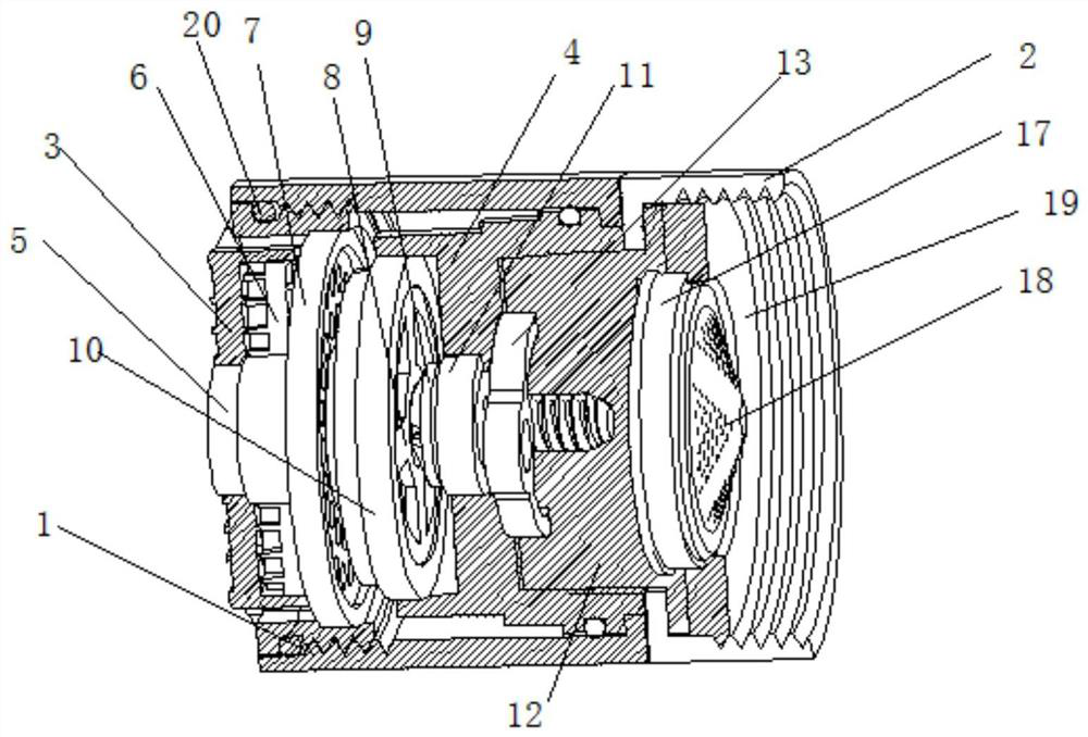
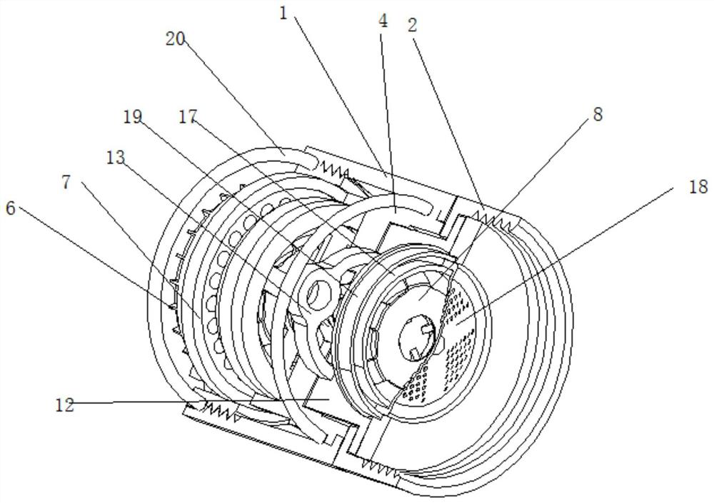
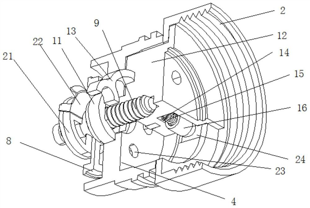
[0025] A spray type multifunctional water outlet device, such as Figure 1-Figure 5 As shown, it includes a front spray shell 1, the rear part of the front spray shell 1 is rotatably connected with a rear spray shell 2, the inner wall of the front spray shell 1 is threadedly connected with a spray seat 3, and the inner wall of the front spray shell 1 is welded with a fixed pillar 4 , the inner wall of the spray seat 3 is rotatably connected with a turntable 5, the surface of the turntable 5 is welded with a shunt net 6 and a shunt disc 7, the inner wall of the turntable 5 is clamped with a large water diversion seat 8, and the rear part of the large water diversion seat 8 is welded with a screw 9 , the rear part of the water seat 8 is slidingly connected with a sealing column 10, the surface of the screw 9 is sleeved with a connecting column 11, the surface of the screw 9 is welded with a fixed seat 12, and the inside of the fixed seat 12 is clamped with a valve disc 13, and th...

Embodiment 2

[0030] Such as Figure 4 As shown, the inside of the fixed seat 12 is provided with a sliding groove 14, the inner wall of the sliding groove 14 is welded with a spring 15, and the bottom end of the spring 15 is welded with a bullet post 16. By setting the sliding groove 14, the spring 15 and the bullet post 16 are fixed on the The effect inside the fixed seat 12, and the bullet column 16 is constantly moving in and out under force when it is in contact with the inner wall of the fixed post 4 during the rotation of the fixed seat 12 .

[0031] In this embodiment, the bullet post 16 is slidably connected to the inner wall of the sliding groove 14, the surface of the bullet post 16 is slidingly connected to the inner wall of the fixed seat 12, and the surface of the bullet post 16 is engaged with the inner wall of the card slot 24. 16 is slidably connected to the inner wall of the sliding groove 14 to achieve the effect of fixing the sliding track of the bullet post 16, and to p...


PUM


Abstract

The invention relates to the technical field of bubblers, in particular to a spray type multifunctional water outlet device. The device comprises a front spraying shell, the rear portion of the frontspraying shell is rotationally connected with a rear spraying shell, the inner wall of the front spraying shell is in threaded connection with a spraying base, a fixed column table is welded to the inner wall of the front spraying shell, and a rotary table is rotationally connected to the inner wall of the spraying base; and a large water dividing base is clamped to the inner wall of the rotary table, a screw is welded to the rear portion of the large water dividing base, the surface of the screw is sleeved with a connecting column, a fixing base is welded to the surface of the screw, and a valve disc is clamped into the fixing base. According to the spray type multifunctional water outlet device, the front spraying shell is twisted, the fixed column table welded to the inner wall of the front spraying shell and the spraying base in threaded connection with the inner wall of the front spraying shell are driven to rotate synchronously, and the spraying base makes sliding contact with the rotary table, a flow dividing net and a flow dividing disc in the rotating process and is subjected to certain position change, so that the effect of changing the water flow spraying direction is achieved through rotation of the spraying base.

Description

technical field [0001] The invention relates to the technical field of bubblers, in particular to a spray-type multifunctional water outlet device. Background technique [0002] The bubbler can be used in the shower and is a common device in the bathroom. There are three types: the first type is portable, which can be held in the hand and showered at will. The bracket has a fixed function. The second overhead type, generally known as the shower, refers to this fixed structure. The head is fixed at the top of the head, and the bracket is inserted into the wall. , does not have the lifting function, and the angle of movement up and down is more flexible. In the third position, the shower is hidden in the wall, spraying the body sideways to clean and massage. [0003] Showers have become a must-have in life, and the spraying methods of common showers on the market are fixed. Generally, the speed and direction of water output from the nozzle are determined according to the size...

Claims


Application Information

Patent Timeline
IPC IPC(8): E03C1/08E03C1/086
CPCE03C1/08E03C1/086
Inventor 钟杰荣
Owner 开平市玛格纳卫浴有限公司
Why Eureka
Try Eureka