Handheld low-temperature plasma jet device and use method thereof

A low-temperature plasma and jet device technology, applied in plasma, electrotherapy, electrical components, etc., can solve problems such as unfavorable hand-held operation, arm fatigue and soreness, and physical exertion, so as to avoid secondary injuries and arm fatigue , improve the effect of friction

Pending Publication Date: 2021-10-22
汪嵘
View PDF1 Cites 0 Cited by
  • Summary
  • Abstract
  • Description
  • Claims
  • Application Information

AI Technical Summary

Problems solved by technology

[0003] The low-temperature plasma therapy instrument disclosed in the existing published application CN201910836776.X has structures such as a plasma generator, a radio frequency source, an argon gas bottle, and a helium gas bottle. The gas mixing tank is connected, the gas mixing tank is connected with the plasma generator to provide mixed gas, the man-machine interface is connected with the gas flow controller and the radio frequency source through PLC, and the gas flow controller and the radio frequency source are respectively controlled, and the radio frequency The source is connected to the plasma generator for plasma generation. This method can realize irradiation treatment on the skin of the patient's affected area, but there are many structures and it is more troublesome to use;
[0004] The handle of the existing low-temperature plasma jet device is relatively fixed to the jet device. When it is used for a long time, the arm is overworked and sore, which is unfavorable for handheld operation. The existing wind plasma jet device has a fixed structure and can only Sweep the wound by swinging the arm. It cannot be sprayed in a large area, which will consume a lot of physical strength and increase the work intensity of the medical staff.

Method used


Image

  • Handheld low-temperature plasma jet device and use method thereof
  • Handheld low-temperature plasma jet device and use method thereof
  • Handheld low-temperature plasma jet device and use method thereof

Examples


Embodiment approach

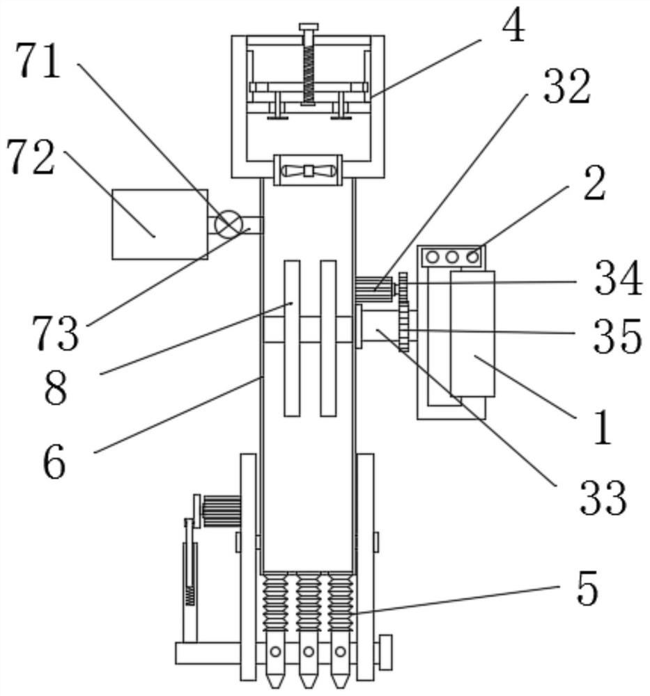
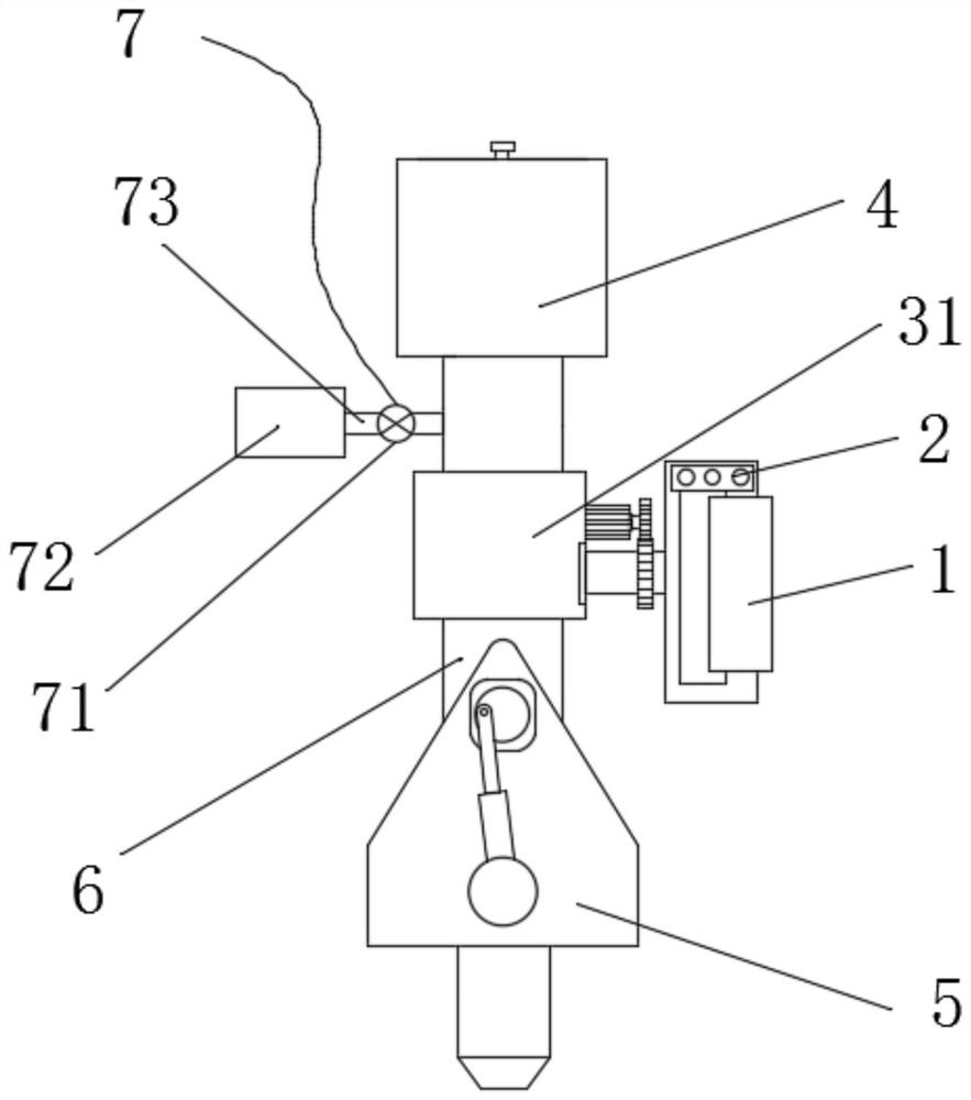
[0035]As an embodiment of the present invention, the driving gear 34 and the matching gear 35 are arranged side by side, the driving gear 34 and the matching gear 35 are mutually meshing structures, the installation cylinder 31 is set on the air cylinder 6, and the handle 1 is wrapped with a scrub sponge. When working, the rotating motor 32 drives the driving gear 34 to rotate. Under the meshing cooperation of the matching gear 35, the rotation of the rotating shaft 33 can be realized, and the relative angle between the handle 1 and the air cylinder 6 can be changed to stabilize For transmission, the handle 1 is provided with a scrub sponge, which can increase the friction between the palm and the handle 1, and can improve the stability of the grip.

[0036] As an embodiment of the present invention, the swing structure 5 includes a fixed frame 51, and the bottom of the fixed frame 51 is pierced with a swing shaft 54, and a plurality of spray heads 53 are anchored on the swing ...


PUM


Abstract

The invention discloses a handheld low-temperature plasma jet device and a use method thereof. The handheld low-temperature plasma jet device comprises a handle, a switch assembly, a rotating structure, a flow slowing structure, a swinging structure, an air duct, an air supplementing structure and a plasma pulser; the flow slowing structure is installed at the top end of the air duct; the rotating structure is adopted, during the use of the device, the surface side of the handle is held, frosted sponge is arranged on the handle, the friction force between the palm and the handle can be improved, the handheld stability can be improved; a motor is powered on, a driving gear is driven to rotate, and under cooperation of a matched gear, rotation of a rotating shaft can be achieved; and by changing the relative included angle between the handle and the air duct, the spraying direction of the air duct can be changed while a proper handheld position is guaranteed, the handheld stability is improved, arm fatigue caused by the fact that an arm keeps one action for a long time is avoided, the holding direction of the handle can be changed randomly, the holding direction of the arm can be adjusted randomly, and the arm can be better protected, and the stability of the handheld mode is improved.

Description

technical field [0001] The invention relates to the technical field of medical equipment, in particular to a hand-held low-temperature plasma jet device and a use method thereof. Background technique [0002] Dielectric barrier discharge can generate stable low-temperature plasma under atmospheric pressure. Compared with other low-temperature plasma generation methods, it is more suitable for large-scale industrial production. It has broad application prospects and has attracted the attention of many researchers. Especially in recent years, low-temperature plasma technology has been widely studied and applied in the field of biomedicine. People are trying to use plasma to replace or assist drugs and traditional medical methods to achieve better therapeutic effects, which can not only avoid The side effects of drugs on the human body will not cause damage to the environment; [0003] The low-temperature plasma therapy instrument disclosed in the existing published applicati...

Claims


Application Information

Patent Timeline
Patent Type & Authority Applications(China)
IPC IPC(8): H05H1/24A61N1/44
CPCH05H1/2406A61N1/44
Inventor 汪嵘
Owner 汪嵘
Why Eureka
Try Eureka