Novel ball valve structure

A ball valve, a new type of technology, applied in the field of regulating ball valves, can solve the problems of poor sealing effect of the ball valve structure, inability to disassemble, and single use method.

Inactive Publication Date: 2020-09-22
CHANGZHOU INST OF TECH
View PDF0 Cites 0 Cited by
  • Summary
  • Abstract
  • Description
  • Claims
  • Application Information

AI Technical Summary

Problems solved by technology

[0004] The purpose of the present invention is to provide a new type of ball valve structure, which aims to improve the structure of the existing ball valve, which can only be used for simple on-off adjustment during use. When the internal valve core of the ball valve cannot rotate, the traditional ball valve It cannot be used normally, and it often needs to be disassembled as a whole. In some special environments, if the pressure cannot be released in advance, it is often impossible to disassemble. At the same time, the existing ball valve structure has poor sealing effect and the use method is relatively simple.

Method used


Image

  • Novel ball valve structure
  • Novel ball valve structure
  • Novel ball valve structure

Examples


Embodiment Construction

[0029] In order to make the purpose, technical solutions and advantages of the embodiments of the present invention clearer, the technical solutions in the embodiments of the present invention will be clearly and completely described below in conjunction with the accompanying drawings in the embodiments of the present invention. Obviously, the described embodiments It is some embodiments of the present invention, but not all of them. Based on the implementation manners in the present invention, all other implementation manners obtained by persons of ordinary skill in the art without creative efforts fall within the protection scope of the present invention. Accordingly, the following detailed description of the embodiments of the invention provided in the accompanying drawings is not intended to limit the scope of the claimed invention, but merely represents selected embodiments of the invention. Based on the implementation manners in the present invention, all other implement...


PUM


Abstract

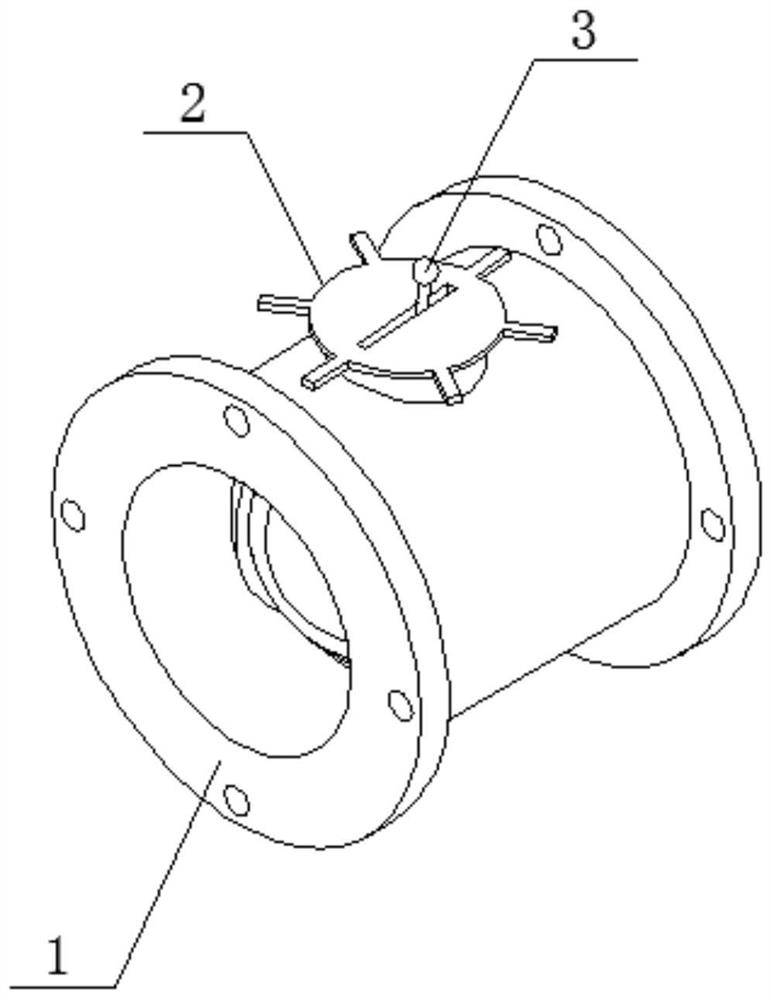
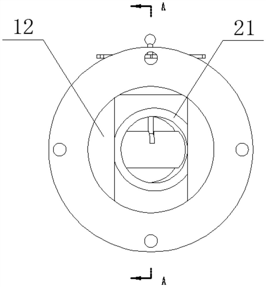
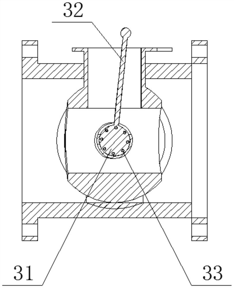
The invention discloses a novel ball valve structure. The novel ball valve structure comprises an outer pipe, a switch valve and an adjusting mechanism, wherein the outer pipe comprises a pipe body and inner arc plates, wherein the inner arc plates are symmetrically arranged on the inner side face of the pipe body, the inner arc plates and the pipe body are integrally formed, the switch valve comprises a flow guide ball and an operating mechanism, the flow guide ball is installed in the inner arc plates, the flow guide ball is rotationally connected with the inner arc plates, the operating mechanism is fixedly installed at the upper end of the flow guide ball, a user can stably drive a stand column to rotate through an operating panel conveniently in an actual using process, then the purpose of rotating the flow guide ball is achieved, when a through-flow hole rotates to be consistent with the direction of the pipe body, it is guaranteed that the ball valve can stably conduct through flow in use, when the through-flow hole rotates to be mutually perpendicular to the direction of the pipe body, the through-flow hole can match with the inner arc plates in a sealed mode, and thereforeit can be guaranteed that liquid inside the pipe body is stopped.

Description

technical field [0001] The invention relates to the technical field of regulating ball valves, in particular to a novel ball valve structure. Background technique [0002] The ball valve is defined as: the opening and closing part (ball) is driven by the valve stem, and the valve rotates around the axis of the ball valve. It can also be used for fluid regulation and control. Alloy metal valve seats have a strong shear force, especially suitable for media containing fibers, tiny solid particles, etc., and the multi-way ball valve can not only flexibly control the confluence, diversion, and flow direction switching of media on the pipeline , At the same time, any channel can be closed to connect the other two channels. Generally, this type of valve should be installed horizontally in the pipeline. Ball valves can be divided into pneumatic ball valves, electric ball valves and manual ball valves. [0003] The inventor of the present application found that the existing ball val...

Claims


Application Information

Patent Timeline
Patent Type & Authority Applications(China)
IPC IPC(8): F16K5/06F16K5/08F16K31/60F16K39/06
CPCF16K5/0605F16K5/0647F16K5/0689F16K5/08F16K31/60F16K39/06
Inventor 陈琳徐康张信华黄炜李柏锦曹文彬
Owner CHANGZHOU INST OF TECH
Why Eureka
Try Eureka