Three-dimensional liquid-solid two-phase flow detection device and method based on electrical tomography
An electrical tomography and detection device technology, applied in the field of flow and concentration measurement in the process of dredging medium transportation, can solve problems such as lack of effective technology, application scenarios, and implementation methods that are not suitable for liquid-solid two-phase flow in industrial pipelines. The effect of reducing the amount of calculation and improving the accuracy
- Summary
- Abstract
- Description
- Claims
- Application Information
AI Technical Summary
Problems solved by technology
Method used
Image
Examples
Embodiment 1
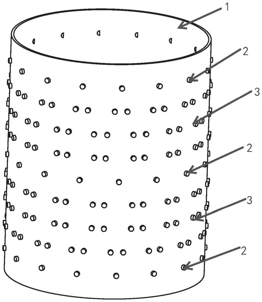
[0038] Such as figure 1 As shown, the three-dimensional liquid-solid two-phase flow detection device based on electrical tomography of the present invention is characterized in that it includes: a delivery pipeline 1, three sets of first electrode arrays 2 and several sets of second electrode arrays 3; Both the first electrode array 2 and several second electrode arrays 3 are used to establish a sensitive field. By applying an excitation signal to one end of a pair of electrodes and detecting a voltage or current signal on the remaining electrodes, it can be obtained that the internal transport of the pipeline 1 is The properties of the medium change.
[0039]The first electrode array 2 is used to establish a sensitive field. By applying an excitation signal to one end of a pair of electrodes and detecting a voltage or current signal on the remaining electrodes, the characteristic change of the conveying medium inside the conveying pipeline 1 can be obtained. In order to achi...
Embodiment 2
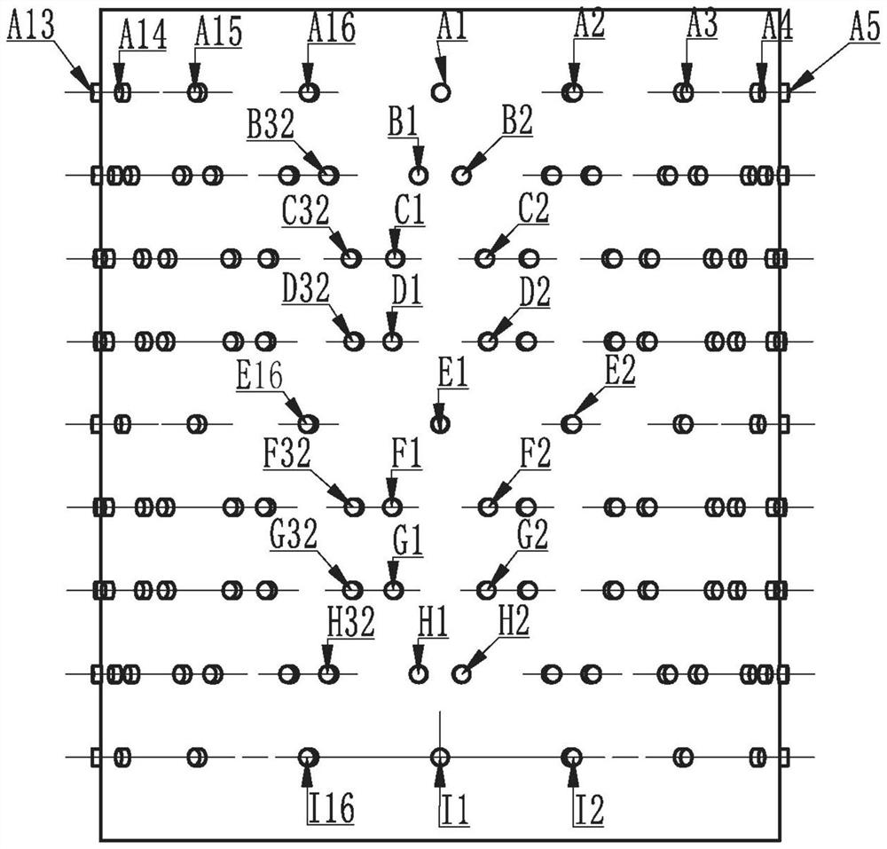
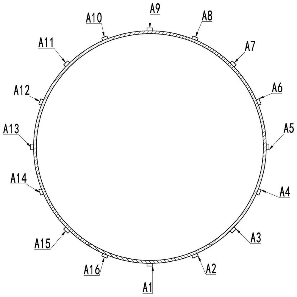
[0050] On the basis of Embodiment 1, this embodiment provides an actual application case. Taking the common 16-electrode sensor arrangement for industrial measurement as an example, that is, N=1, M=16, P=32, S=6, Z=3, a total of 9 layers of electrode arrays need to be installed on a section of pipeline 1, such as figure 2 As shown, they are respectively marked as A layer, B layer, C layer, D layer, E layer, F layer, G layer, H layer and I layer, wherein A layer is the first group of first electrode array 2, and E layer is the first electrode array 2. Two groups of first electrode arrays 2, layer I is the third group of first electrode arrays 2; as figure 2 , image 3 and Figure 4 As shown, the number of electrodes in each layer is 16, 32, 32, 32, 16, 32, 32, 32 and 16 respectively. Each layer of electrodes is labeled A1-A16, B1-B32, C1-C32, D1-D32, E1-A16, F1-F32, G1-G32, H1-H32 and I1-I32, of which A layer, E layer and I Layer 16 electrodes are arranged at equal interv...
PUM
 Abstract
Description
Claims
Application Information
 - R&D
- Intellectual Property
- Life Sciences
- Materials
- Tech Scout
- Unparalleled Data Quality
- Higher Quality Content
- 60% Fewer Hallucinations
Browse by: Latest US Patents, China's latest patents, Technical Efficacy Thesaurus, Application Domain, Technology Topic, Popular Technical Reports.
© 2025 PatSnap. All rights reserved.Legal|Privacy policy|Modern Slavery Act Transparency Statement|Sitemap|About US| Contact US: help@patsnap.com


