Construction machinery control cabinet

A technology for construction machinery and control cabinets. It is applied in the direction of pull-out switch cabinets, switchgear, electrical components, etc. It can solve problems such as equipment failure, falling and jamming in the moving slot of the drawer, and inconvenient movement of the drawer, so as to achieve improvement. Ability to move, improve stretching effect, avoid wear and tear effect

Active Publication Date: 2020-09-22
深圳市君安电气设备有限公司
View PDF15 Cites 0 Cited by
  • Summary
  • Abstract
  • Description
  • Claims
  • Application Information

AI Technical Summary

Problems solved by technology

[0003] In view of the above, when installing mechanical equipment for mechanical control, it is necessary to pull the drawer outward. Because there is a lot of dust on the construction site, it is easy to accumulate in the moving groove of the drawer during the process of flying around, which makes the movement of the drawer inconvenient. Finally, when the drawer is pushed back inward, some of the components or lines of the mechanical equipment will easily hit the side of the control cabinet and the drawer, or fall and get stuck in the moving slot of the drawer, which will easily cause equipment failure. The invention provides a construction machinery control cabinet

Method used


Image

  • Construction machinery control cabinet
  • Construction machinery control cabinet
  • Construction machinery control cabinet

Examples


Embodiment 1

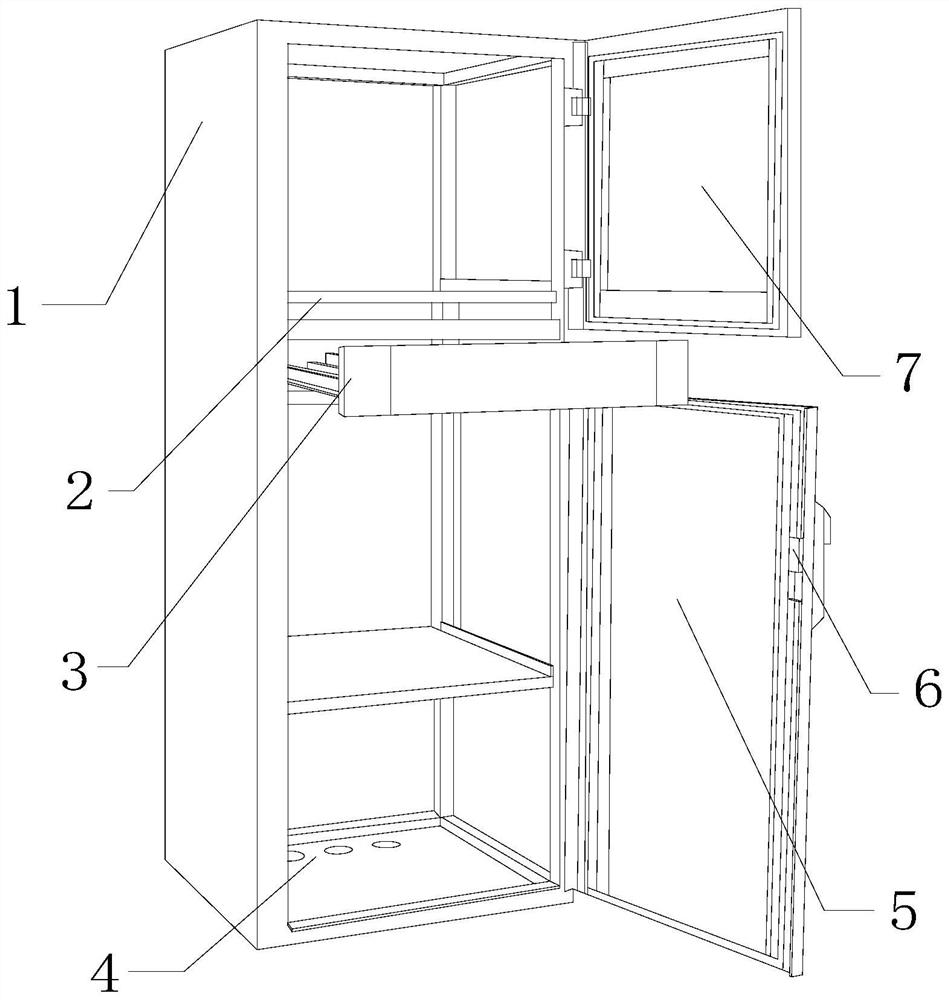
[0025] Such as Figure 1-Figure 4 Shown:

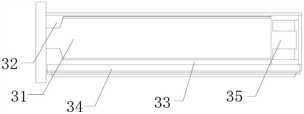
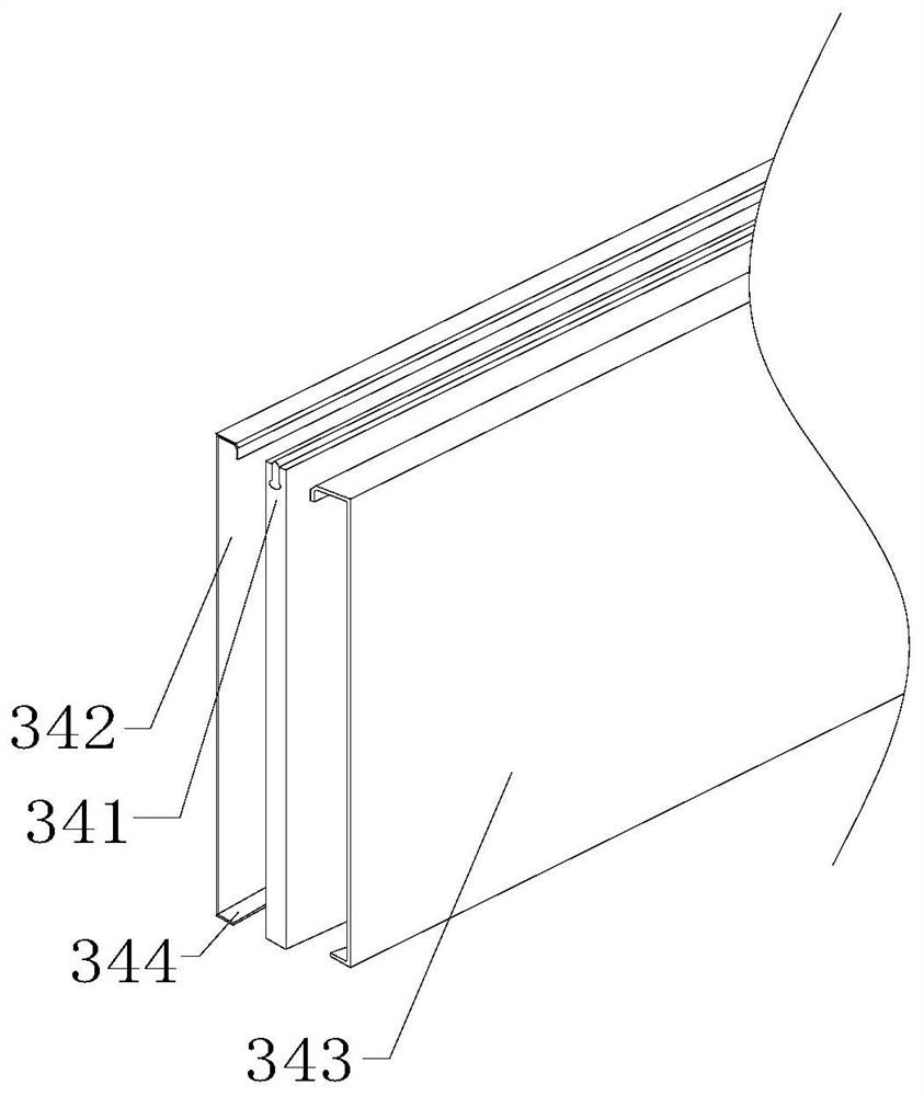
[0026] The invention provides a control cabinet for construction machinery, the structure of which includes a control cabinet box 1, a placement board 2, a drawer 3, a hollow bottom plate 4, a lower cabinet door 5, a lock 6, an upper cabinet door 7, and the upper cabinet door 7 The hinge is connected to the top of the control cabinet 1, the placement plate 2 is bolted to the top of the drawer 3, the hollow bottom plate 4 is embedded and connected to the bottom of the control cabinet 1, and the lock 6 is nested and connected to the lower cabinet door 5 At the side end, the lower cabinet door 5 is hinged to the position below the control cabinet 1, and the drawer 3 is movably engaged in the middle and upper section inside the control cabinet 1. The drawer 3 mainly includes a drawer box 31, a guide rail baffle 32, Side guide rail 33, sliding mechanism 34, auxiliary pusher 35, described auxiliary pusher 35 is embedded and connected to th...

Embodiment 2

[0032] Such as Figure 5-Figure 8 Shown:

[0033]The present invention provides a construction machinery control cabinet. The auxiliary pusher 35 mainly includes a pad 351, an extension device 352, a shaft plate 353, a shaft rod 354, an insert block 355, a stopper 356, and a spring rod 357. The extension device 352 is nested and connected between the pads 351, the extension device 352 is attached to the front of the shaft 354, the elastic rod 357 is embedded and connected to the rear of the insert 355, and the shaft plate 353 is bolted to the side of the shaft 354 Square, the shaft 354 is fixedly connected under the plug 355, the elastic rod 357 is riveted to the front end of the stopper 356, the stopper 356 is connected with the shaft 354, and the auxiliary pusher 35 has a stepped structure , and the stopper 356 at the upper end is provided with three elastic rods 357, which are arranged and installed at the front end of the stopper 356. The elastic rods 357 can assist the e...


PUM


Abstract

The invention discloses a construction machinery control cabinet. The control cabinet structurally comprises a control cabinet box, a placing plate, a drawer, a hollow bottom plate, a lower cabinet door, a lock catch and an upper cabinet door, the drawer is movably clamped inthe middle upper section in the control cabinet box; the drawer comprises a drawer box, a guide rail baffle, a side guide rail, a sliding mechanism and an auxiliary booster; the auxiliary booster is fixedly connected to the rear side of the drawer box in an embedded mode. The sliding mechanism is fixedly connected to the lower end of the drawer; the drawer box is matched with guide of the side guide rail and the guide rail baffle plate in the lateral side, rolling balls can improve the moving capacity of asliding plate; therefore, other mechanical circuits and parts are prevented from being impacted in the pulling process; when the drawer box is retracted, the sliding plate is separated or damaged, anelastic rod auxiliary extension device extends, and apush piece is matched with the guide rod to move anelastic strip and an extension hemisphere, so that the drawer box can well place mechanical equipment, and when the drawer box is retracted, the elastic strip can relieve the rebound impact pressure, and the situation that the drawer box is damaged due to the push-back pressure is avoided.

Description

technical field [0001] The present invention relates to the field of construction machinery, and more specifically, relates to a construction machinery control cabinet. Background technique [0002] The construction machinery control cabinet is installed on the construction site and assembles switchgear, measuring instruments, protective appliances and auxiliary equipment in a closed or semi-closed metal cabinet according to the electrical wiring requirements. Its layout should meet the requirements of the normal operation of the power system and facilitate maintenance. It does not endanger the safety of people and surrounding equipment. When installing mechanical equipment for mechanical control, it is necessary to pull the drawer outward. Because there is a lot of dust on the construction site, it is easy to accumulate in the moving groove of the drawer during the process of flying around. The movement of the drawer is inconvenient, and after installation, when the drawer ...

Claims


Application Information

Patent Timeline
Patent Type & Authority Applications(China)
IPC IPC(8): H02B11/127H02B11/173
CPCH02B11/127H02B11/173
Inventor 邵彬
Owner 深圳市君安电气设备有限公司
Why Eureka
Try Eureka