Interface screw

An interface screw and blade technology, applied in the field of medical devices, can solve the problems of ligament fatigue failure, easy deformation or fracture, insufficient fixation strength and creep resistance, etc., and achieves the effect of firm screw fixation and not easy to fall off.

Pending Publication Date: 2020-09-25
GUANGZHOU SUN SHING BIOTECH CO LTD
0 Cites 0 Cited by

AI-Extracted Technical Summary

Problems solved by technology

However, the fixing strength and creep resistance of the current commercially available interface screws are still insufficient.
[0003] The interface screw has the following problems: the interface screw is a hollow conical screw, and its nail head is thin, and it is easy to deform or break under the action of torsion during the screw-in process; when the...

Method used

Anti-slip lines 4 are zigzag distributed on the blades, and anti-slip lines 4 are inclined towards the direction away from the bottom of the sheath 2, so that the serrations and ligaments are at a small angle during implantation, reducing friction, and the serrations and ligaments are at a large angle after implantation , increasing the friction.
The interface screw needs higher rigidity, a degradation time of more than 2 years, and needs to be able to guide bone tissue regeneration, so take PLLA as the main material, add PLA-TMC to regulate and control the degradation time, and add hydroxyapatite or β -TCP or a mixture of hydroxyapatite and β-TCP so that the product has the effect of guiding bone tissue regeneration.
[0022] A plurality of blades 1, the number of blades is not limited to four blades shown in the figure, the bottom of the sheath 2 is connected...

Abstract

The invention provides an interface screw which improves the structure of an existing interface screw and is additionally provided with a porous sheathing canal so as to prevent ligament cutting forcewhen the screw is implanted. The interface screw is characterized in that the interface screw penetrates through the sheathing canal. The sheathing canal comprises: a sheathing bottom which is located at the bottom of the sheathing canal, wherein a through hole allowing the interface screw to penetrate through is formed in the sheathing bottom; and blades which are connected to the sheath bottom.Each blade is provided with a sheath hole and anti-skid lines, the sheath hole is located in the upper end, away from the sheath bottom, of each blade, the anti-skid lines are distributed on each blade in a sawtooth shape, and the anti-skid lines incline in the direction away from the sheath bottom.

Application Domain

DiagnosticsFasteners

Technology Topic

PhysicsEngineering +1

Image

  • Interface screw

Examples

  • Experimental program(1)

Example Embodiment

[0018] The invention provides an interface screw, which improves the structure of the existing interface screw and adds a porous sheath, thereby preventing the cutting force of the ligament when the screw is implanted.
[0019] The technical solutions in the embodiments of the present invention will be clearly and completely described below in conjunction with the accompanying drawings in the embodiments of the present invention. Obviously, the described embodiments are only a part of the embodiments of the present invention, rather than all the embodiments. Based on the embodiments of the present invention, all other embodiments obtained by those of ordinary skill in the art without creative work shall fall within the protection scope of the present invention.
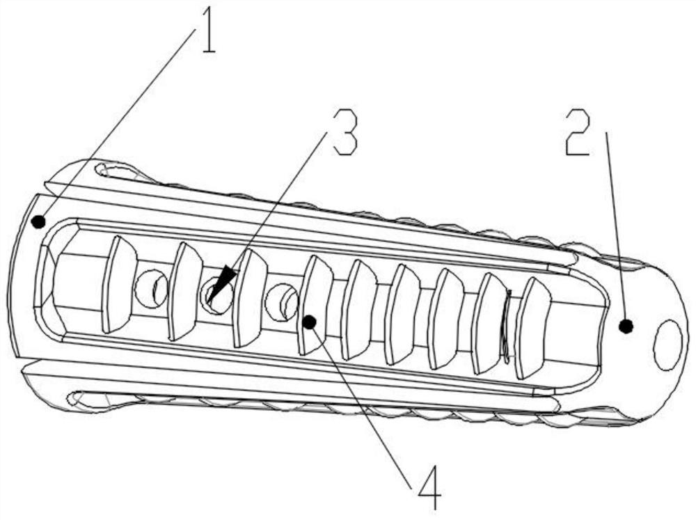
[0020] Such as figure 1 As shown, the sheath includes:
[0021] The sheath bottom 2 is located at the bottom of the sheath tube. The sheath bottom 2 is provided with a through hole for the penetration of ligaments and the penetration of interface bone nails;
[0022] The number of blades 1 is not limited to the four blades shown in the figure, and the sheath bottom 2 is connected to the blade 1. The blade 1 is the main support structure of the sheath, which protects the ligament and prevents the thread of the interface screw from cutting the ligament during implantation. When the sheath is implanted, the blade shrinks to reduce the friction on the ligament. When the interface screw is implanted Expand the blade to increase the pressure of the blade on the ligament, thereby increasing the overall fixing strength.
[0023] The blade 1 is provided with a sheath hole 3 and an anti-skid pattern 4. The sheath hole 3 can be located at the upper end of the blade 1 away from the sheath bottom 2, which is convenient for fixing the screw after the bone tissue grows in, and provides a microenvironment for the degradation of the interface screw
[0024] The anti-slip pattern 4 is distributed on the blade in a zigzag pattern, and the anti-slip pattern 4 is inclined away from the sheath bottom 2, so that the serrations and ligaments are at a small angle during implantation, which reduces friction. After implantation, the serrations and ligaments are at a large angle and increase friction.
[0025] The sheath tube needs higher impact strength, so PCL material, or PLGA material, or PGA-TMC material or PLGA-TMC material is used, preferably PLGA material, such as PLGA8218. The GA in PLGA can improve the material's higher impact strength, and LA provides the material with a longer degradation time. The degradation time of PLGA8218 is 12 to 18 months, which can meet the maintenance time of the high fixing strength of the interface screw. It ensures rapid degradation so that the inorganic salt in the screw inside the sheath quickly contacts the bone tissue and plays a role in guiding bone tissue regeneration.
[0026] Interface screws need high rigidity, degradation time of more than 2 years, and need to be able to guide bone regeneration. Therefore, PLLA is used as the main material, PLA-TMC is added to control the degradation time, and hydroxyapatite or β-TCP or The mixture of hydroxyapatite and β-TCP makes the product have the effect of guiding bone tissue regeneration.
[0027] The interface screw is made of polylactide and trimethylene carbonate copolymer and BCP/β-TCP blend injection molding, which can induce bone tissue regeneration.
[0028] The interface screw adopts the orientation orientation process to orient the screw along the thread direction, improve the mechanical strength of the interface screw, reduce the friction force when screwing in, and increase the friction force when screwing out.
[0029] The interface screw preparation method is:
[0030] Firstly, the blank material is injected, and the required raw material volume and blank material size are calculated according to the size of the interface screw, and hollow cylindrical blank material is prepared by injection molding.
[0031] Then perform variable diameter forging to prepare oriented screws. Forging requires designing and preparing a variable diameter forging die. The upper die has the same outer diameter as the blank, and the lower die has the same size as the screw. There is a stainless steel thimble in the middle of the whole die, and the shape and size are the center of the interface screw. The holes are consistent. During forging, the blank is placed in the cavity and the temperature is raised to higher than the glass transition temperature of the blank material and lower than the melting temperature of the blank material, so that the blank is in a highly elastic state; the bottom of the forging equipment is equipped with a variable-speed turntable, during the forging process Among them, the variable speed turntable is programmed to rotate at a constant speed or at a variable speed, driving the lower die to rotate at a constant speed or at a variable speed. During the forging process, the blank material is subjected to the upward shearing force generated by the diameter reduction of the die and the circumferential direction generated by the rotation of the lower die. The shearing force cooperates to produce a shearing force along the thread direction, and finally the blank material is oriented along the thread direction.
[0032] The raw material of the interface screw can be polylactide, polycaprolactone, polyglycolide, polytrimethylene carbonate and other absorbable polyester homopolymers or copolymers, or these homopolymers or copolymers and Blends of inorganic materials such as hydroxyapatite or bioceramics.
[0033] The injection temperature is above the melting temperature of the raw materials used and below the degradation temperature. For example, polylactide can be injected at 200-230°C.
[0034] The forging temperature should be higher than the glass transition temperature of the raw materials used, and lower than the melting temperature of the raw materials used. For example, polylactide should be forged at 65-190°C.
[0035] The forging pressure is 5-100T, preferably 20-60T. The forging speed is 0.1 to 15 m/s, preferably 1 to 5 m/s. The forging time is 0.1-10 min, preferably 0.5-5 min. The rotation rate of the chassis is 0.1-100 r/min, preferably 1-30 r/min. The cooling temperature after forging is 0-50°C, preferably 0-25°C. Cooling time: 1-30min, preferably 1-10min.
[0036] The size of the sheath tube is complicated, and it is difficult to directly inject with the traditional injection molding process. Therefore, a simple processing method for injection molding using the principle of parameter control and polymer material warpage deformation has been developed, which greatly reduces the processing difficulty of the sheath tube And processing time.
[0037] The simple processing technology of sheath mainly includes:
[0038] (1) Keep the front mold at a higher temperature (above the glass transition temperature of the material, such as 110°C), and the back mold is in a low temperature state through cold water circulation to ensure that different positions of the injection molded parts are in different states
[0039] (2) The sheath tube has a four-leaf structure, and the four blades of the sheath tube are pressed into a nearly flat state for injection molding.
[0040] (3) During injection, the blade faces the rear mold and the sheath bottom faces the front mold.
[0041] (4) After the injection molding is completed, the blade toward the rear mold quickly cools and becomes hard, while the sheath bottom toward the front mold cools slowly and is still above the glass transition temperature. Control the pressure holding time <5s and quickly use the top pin to align the sheath at the bottom of the sheath. When the tube is ejected, the bottom of the sheath tube is warped and deformed toward the blade due to the force, and finally a three-dimensional sheath tube is obtained.
[0042] (5) In order to better control the warpage angle of the blade, a manipulator is designed on the side of the injection molding machine. The manipulator is tubular and easy to disassemble. The pipe diameter is consistent with the expected maximum diameter of the outer sheath of the sheath. The hot channel is controlled by constant temperature water circulation to keep the temperature above the glass transition temperature of the sheath material. After the front and rear molds of the injection molding machine are separated, the manipulator quickly moves to a position where the center of the tube is flush with the center of the sheath, and the thimble moves to eject the sheath to the manipulator In the middle part, during the ejection process, the sheath tube can be easily deformed to the original three-dimensional structure due to the obstruction of the sheath tube wall and the temperature effect.
[0043] The above embodiments are only used to illustrate the technical solutions of the present invention, not to limit them; although the present invention has been described in detail with reference to the foregoing embodiments, a person of ordinary skill in the art should understand that: The recorded technical solutions are modified, or some of the technical features are equivalently replaced; these modifications or replacements do not cause the essence of the corresponding technical solutions to deviate from the spirit and scope of the technical solutions of the embodiments of the present invention.

PUM

no PUM

Description & Claims & Application Information

We can also present the details of the Description, Claims and Application information to help users get a comprehensive understanding of the technical details of the patent, such as background art, summary of invention, brief description of drawings, description of embodiments, and other original content. On the other hand, users can also determine the specific scope of protection of the technology through the list of claims; as well as understand the changes in the life cycle of the technology with the presentation of the patent timeline. Login to view more.

Similar technology patents

Waterproofing slurry

InactiveCN105036609ANot easy to fall offCuring drying time is short
Owner:QINGDAO ENGAO MOTION CONTROL TECH

Classification and recommendation of technical efficacy words

Why Eureka
Try Eureka