Foam atomizer and wellbore structure for bubble exhaust and gas production of natural gas well and gas production method

An atomizer and natural gas technology, applied in the field of multiphase flow, can solve the problems of high price of electric submersible pump drainage system, short life of unit equipment, increase of back pressure at the bottom of the well, etc., to achieve improved atomization efficiency, simple structure, The effect of deep drilling

Active Publication Date: 2020-09-25
XI AN JIAOTONG UNIV
View PDF6 Cites 5 Cited by
  • Summary
  • Abstract
  • Description
  • Claims
  • Application Information

AI Technical Summary

Problems solved by technology

However, the existing technology is not perfect enough, and there are still deficiencies in the actual application of the project: for example, when the gas-lift drainage lifts the liquid upward, it will also react on the formation, increasing the back pressure at the bottom of the well, and causing gas deficiency; The price of the electric submersible pump drainage system is expensive, and the unit energy consumption is large. When the bottom fluid contains more gas, as the liquid enters the electric submersible pump, the efficiency will drop sharply, and the unit equipment will The life in the wellbore is short; the foam drainage gas recovery process cannot rely solely on it to complete the drainage operation after the pressure in the well drops to a certain level

Method used


Image

  • Foam atomizer and wellbore structure for bubble exhaust and gas production of natural gas well and gas production method
  • Foam atomizer and wellbore structure for bubble exhaust and gas production of natural gas well and gas production method
  • Foam atomizer and wellbore structure for bubble exhaust and gas production of natural gas well and gas production method

Examples


Embodiment

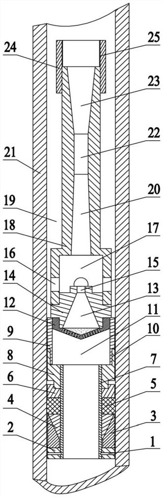
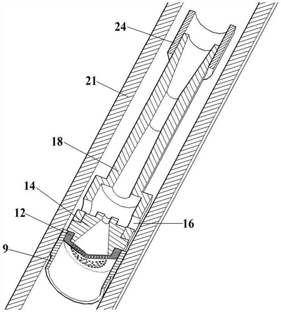
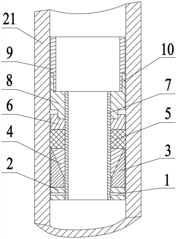
[0039] see figure 1 with figure 2 , the present embodiment is used for the foam atomizer of natural gas well bubble row gas recovery, mainly by atomizer inlet section barrel 9, porous cone plate 12, nozzle barrel 14 and atomizer vortex section barrel 18 composition; The structure of the foam atomizer includes an atomizer inlet 11, a porous cone plate 12, a nozzle inlet 13, a nozzle throat 15, a swirl hole 16, a nozzle rear cavity 17, a receiving chamber 20, and a mixing chamber from bottom to top. 22. The diffusion chamber 23 and the connecting section 24 between the atomizer and the downhole operation tool; the outer wall of the cylinder body 9 of the inlet section of the atomizer is provided with the connecting thread 10 between the atomizer and the packer; the porous cone plate 12 is distributed with The metal cone plate with thin round holes, the thin round holes are atomization holes, used for preliminary atomization, the plane of the cone plate is perpendicular to the ...


PUM


Abstract

The invention discloses a foam atomizer and wellbore structure for bubble exhaust and gas production of a natural gas well and a gas production method. The foam atomizer comprises a porous cone plate,a nozzle barrel and an atomizer vortex section barrel, wherein the nozzle barrel is provided with a nozzle inlet, the nozzle inlet extends from one end of the nozzle barrel to the other end of the nozzle barrel, the nozzle inlet is a linear tapered cone pipe, a nozzle throat is arranged on the portion, at the tail end of the small end of the nozzle inlet, of the nozzle barrel, and the porous coneplate is arranged on one side of the big end of the nozzle inlet and is connected with the nozzle barrel; the conical surface of the porous cone plate is uniformly provided with atomizing holes, theaxis of the atomizing holes is parallel to the wall surface of the nozzle inlet, and the sum of the cross-sectional areas of the atomizing holes is not larger than the cross-sectional area of the nozzle throat; and the atomizer vortex section barrel is arranged on one side of the small end of the nozzle inlet and is connected to the nozzle barrel. The foam atomizer and a bubble exhaust and gas extraction process are used in combination so that accumulated liquid in the natural gas well can be more effectively discharged out of a wellbore.

Description

technical field [0001] The invention belongs to the technical field of multiphase flow, and in particular relates to a foam atomizer, a wellbore structure and a gas recovery method used for gas recovery by foam drainage in natural gas wells (also called gas recovery by foam drainage or gas recovery by foam drainage). Background technique [0002] In the process of natural gas extraction, as the extraction time continues, the gradual decline in natural gas production will cause the airflow velocity to continue to decrease, resulting in a decrease in the liquid-carrying capacity of the airflow, unable to carry the fluid at the bottom of the well to the wellhead and eventually stagnated in the wellbore . The effusion continues to accumulate to form a liquid column, which increases the hydrostatic back pressure of the gas reservoir and further reduces the self-spraying energy of the gas well. If this vicious cycle continues, the liquid column in the wellbore will accumulate hig...

Claims


Application Information

Patent Timeline
Patent Type & Authority Applications(China)
IPC IPC(8): B05B7/00E21B43/16
CPCB05B7/0037E21B43/16
Inventor 刘磊高玉堂黄娜邬学利
Owner XI AN JIAOTONG UNIV
Why Eureka
Try Eureka